Advertisement
Table of Contents
- 1 Table of Contents
- 2 Descrip on
- 3 Technical Data
- 4 Moun Ng, Dimensional Drawing
- 5 Important Notes (Including Health & Safety)
- 6 Hardware Overview
- 7 Overview of Configura on Menusyd7010
- 8 Connect the YD7010 to the Power Supply Unit and the PC Via USB
- 9 Connec on Example Hand Controller
- 10 Main Track or Programming Track Connec on
- 11 Example of Connec Ng the Feedback Unit to the 2-Wire Track and Loconet® T
- 12 Connec on Example of the YD6016LN-CS Feedback Unit on the 2-Wire Track, with YD7403 Booster Via Loconet® B
- 13 Warranty
- Download this manual
Advertisement
Table of Contents

Summary of Contents for Yamorc YD7010
- Page 1 YD7010 Multi LAN Protocol Command Station Quick start (2024−05−08) Designed by Karst Drenth Made in Germany Assembled in NL...
-
Page 2: Table Of Contents
Important notes (including Health & Safety) …..………………………………… 5 Hardware overview …………………………………………………………………………. 6 Overview of configura on menusYD7010…………………………………… Connect the YD7010 to the power supply unit and the PC via USB.… 12 Connec on example hand controller…………………………………………………. 12 Main track or programming track connec on……………………………………. 13 Example of connec ng the feedback unit to the 2-wire track and LocoNet®... -
Page 3: Descrip On
The YD7001 has a full programming track. Locomo ves and accessory addresses are controlled either via the YaMoRC tool, a handheld controller, an app or a PC programme (WDP®, Itrain® or similar) Various IR remote controls (e.g. Uhlenbrock®, Piko®DigiFern) can be used to control locomo ves via the integrated IR receiver. -
Page 4: Technical Data
157 mm x 88 mm x 22 mm Hole distance 173,5 mm, 42,5 mm Moun ng The YD7010 is mounted using the four moun ng holes on the side of the housing. Dimension drawing 173,5 mm 157 mm 42,5 mm 88 mm www.yamorc.de... -
Page 5: Important Notes (Including Health & Safety)
Connec on work must always be carried out in a de-energised state. The YD7010 must never be installed near strong heat sources, such as radiators or loca ons exposed to direct sunlight. Therefore, install the YD7010 in a loca on with sufficient ven la on to dissipate the waste heat. -
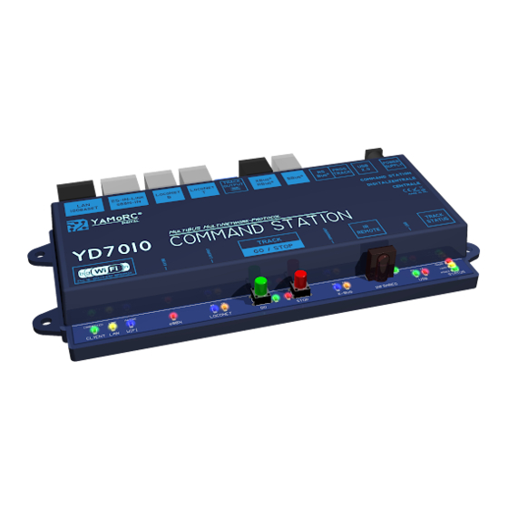
Page 6: Hardware Overview
Max: (60W Output power of the power supply unit) The power supply unit used must comply with protec on class 2. Failure to do so may result in serious damage to the YD7010. The power supply unit must be labelled with this symbol. - Page 7 Orange LED off, no connec on via a network cable. Link Lan **** Orange LED flashes irregularly, indicates that the YD7010 is connected with a network cable to a router, for example, and is exchanging data. — Blue LED off, WiFi deac vated...
- Page 8 YD7010 Hardware overview USB Ac vity indicator Green LED **** Green LED RX, data is being received via USB **** Red LED TX, data is sent via USB Track Status **** Red LED flashes, short circuit detected at Track Out...
-
Page 9: Overview Of Configura On Menusyd7010
Overview of the YD7010 configura on menu The individual configura on menus of the YD7010 are called up simply by clicking on the individual buFons. Further menu items are called up by clicking on the individual tabs. A brief overview of the menu structure is shown here. - Page 10 Overview of the YD7010 configura on menu The individual configura on menus of the YD7010 are called up simply by clicking on the individual buFons. Further menu items are called up by clicking on the individual tabs. A brief overview of the menu structure is shown here.
- Page 11 Overview of the YD7010 configura on menu The individual configura on menus of the YD7010 are called up simply by clicking on the individual buFons. Further menu items are called up by clicking on the individual tabs. A brief overview of the menu structure is shown here.
-
Page 12: Connect The Yd7010 To The Power Supply Unit And The Pc Via Usb
All common handheld controllers for Loconet® (e.g. Uhlenbrock®, Piko®, Digitrax®, etc.) and Xpressnet® (e.g. Lenz®, Roco®, etc.) can be operated directly on the YD7010. However, it is essen al to ensure that the sockets for Loconet® and Xpressnet® are not mixed up. This will result in damage to the YD7010 or the hand controller. -
Page 13: Main Track Or Programming Track Connec On
YD7010 Main track or programming track connec on Track separa on on both sides between main track and programming track www.yamorc.de P 13... -
Page 14: Example Of Connec Ng The Feedback Unit To The 2-Wire Track And Loconet® T
YD7010 Example of connec ng the feedback unit to the 2-wire track and LocoNet® T Con nue LocoNet® Components www.yamorc.de P 14... -
Page 15: Connec On Example Of The Yd6016Ln-Cs Feedback Unit On The 2-Wire Track, With Yd7403 Booster Via Loconet® B
YD7010 Connec on example of the YD6016LN-CS feedback unit on the 2-wire track, with YD7403 booster via LocoNet® B Con nue LocoNet® Components Track separa on on both sides between main track and programming track Command Booster Sta on Note: Always check the track separa on between the control centre and booster as shown here! The measured value displayed must not exceed 0.8 volts! If the voltage... -
Page 16: Warranty
Content of the guarantee/exclusions: The warranty includes, at YaMoRC's discre on, the free repair or free replacement of the defec ve part, which can be proven to be due to design, manufacturing, material or transport faults. For this purpose, you must send the decoder to us properly stamped. Further claims are excluded.
Need help?
Do you have a question about the YD7010 and is the answer not in the manual?
Questions and answers