
Subscribe to Our Youtube Channel
Summary of Contents for Lasertack Sirius 500
- Page 1 Laser Diode Current and Temperature Controller Operation Manual Click to go back to Contents Copyright ©2023 Lasertack GmbH...
- Page 2 Version: 1.0 Date: 03.08.2023 SKU: 01418 Click to go back to Contents Copyright ©2023 Lasertack GmbH...
-
Page 3: Table Of Contents
Setting the Photo Diode Input LD Modulation Settings Overcurent Protection Board TEC Source Setup Temperature Sensor Setup 3.10 Temperature Protection of the Laser Diode and Sirius Driver 3.11 PID Control Loop 3.12 Information Click to go back to Contents Copyright ©2023 Lasertack GmbH... - Page 4 4.2 Instrument Driver Installation 4.3 Firmware Updates 4.4 Communication Protocol Maintenance 5.1 General Remarks 5.2 Supply Voltage 6 Appendix Technical Data Dimensions Certificates Warranty Exclusion of Reliability „End of Life“ Policy Click to go back to Contents Copyright ©2023 Lasertack GmbH...
- Page 5 Lasertack GmbH aims to develop and provide highly reliable, state of the art equipment. You, our customer, can help us to improve our products and services. Please let us know your ideas, suggestions and possible criticism. Warning Sections marked by this symbol explain dangers and might result in per- sonal injury or death.
-
Page 6: General Information
• Temperature protection for Laser Diode and Driver board. • Temperature loop monitoring for laser protection. • USB interface for remote operation. • LabVIEW™ based user interface. • DLL library for implementation. Click to go back to Contents Copyright ©2023 Lasertack GmbH... -
Page 7: Safety
If necessary, ask for replacement packaging. Refer servicing to qualified personnel! Only with written consent from Lasertack GmbH may changes to single components be made or components not supplied by Lasertack GmbH be used. Attention... - Page 8 Lasertack GmbH is not responsible for any radio television interference caused by modifications of this equipment or the substitution or attachment of connecting ca- bles and equipment other than those specified by Lasertack GmbH. The correction of interference caused by such unauthorized modification, substitution or attachment will be the responsibility of the user.
- Page 9 When operated incorrectly, this can cause severe damage to your eyes and health! Be sure to pay strict attention to the safety recommendations of the appropriate laser safety class! This laser safety class is marked on your external laser source used. Click to go back to Contents Copyright ©2023 Lasertack GmbH...
-
Page 10: Protection Of Laser Diodes
· To connect your external automatic protection equipment, e.g. for temperature monitoring · Laser ON/OFF LED (Please refer to section Connecting the interlock and LD ON monitoring) The laser can only be operated with the interlock input being closed. Click to go back to Contents Copyright ©2023 Lasertack GmbH... -
Page 11: Models And Accessories
1.3 Models and Accessories Models: • Sirius 500 0-500 mA • Sirius 5000 100-5000 mA Accessories: • 250 W Power Supply 90-240 VAC. • 450 W Power Supply 100-240 VAC. • Output Adapter Board D-Sub25 to push terminals with current memory chip. -
Page 12: Preparation
Verify that you have received the following items: • Sirius Laser Diode Controller • Optional boards (APC, ITRIP, TEC Controller, Adapter for input/output) • USB-C to USB-A connecting cable Connect the Sirius driver with the power supply. Click to go back to Contents Copyright ©2023 Lasertack GmbH... - Page 13 LD current, internal modulation, APC and ITRIP (OCP) settings TEC voltage, temperature, I and D parameter settings Temperature settings Software and firmware are always subject to be changed without prior notice to provide the best functionality. Click to go back to Contents Copyright ©2023 Lasertack GmbH...
-
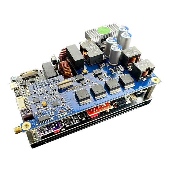
Page 14: 2Basic Elements On The Sirius Board
2.2.2 Basic Elements on the Sirius Board Click to go back to Contents Copyright ©2023 Lasertack GmbH... -
Page 15: Before First Operation
Refer servicing to qualified personnel! Only with written consent from Lasertack GmbH may changes to single components be made or components not supplied by Lasertack GmbH be used. Ensure to use only grounded power supplies. The driver needs to be operated with duly shielded connection cables only. -
Page 16: Connecting Components
3.1 Connecting components Available connecting components are as follows: • Sirius Laser Diode Driver • APC Board • OCP Board • TEC Controller Board • Output Adapter Board Click to go back to Contents Copyright ©2023 Lasertack GmbH... - Page 17 3.1.1 Pin Assignmen of the Laser Controller Input Output Click to go back to Contents Copyright ©2023 Lasertack GmbH...
-
Page 18: Connecting The Laser Diode
Use a separate shielded cables Photo Diode measurement line. The Laser current lines should be as short as possible and as close together as possible (e.g. twisted) to minimize inductance. Click to go back to Contents Copyright ©2023 Lasertack GmbH... - Page 19 Even if the current requirement is below 2A we suggest to use cables where all the pins are connected. For Anode: 4, 5, 17, 18 For Cathode: 6, 7, 19, 20 Click to go back to Contents Copyright ©2023 Lasertack GmbH...
-
Page 20: Connecting A Photodiode
We recommend using shielded “twisted pair“ wiring for the monitor diode current measurement. Note The PD needs to be mounted in reverse. The Cathode of the PD needs to be connected to +5V of the pin 8. Click to go back to Contents Copyright ©2023 Lasertack GmbH... -
Page 21: Connecting Interlock
Furthermore, the interlock LED on the LD Driver will change from solid state (interlock closed) to blinking state (interlock open). The LD output cannot be activated when the interlock loop is open. Click to go back to Contents Copyright ©2023 Lasertack GmbH... - Page 22 The maximum TEC output current for the Sirius Series is 5A. Use only the 1mm² ca- bles. It is highly suggested to use shielded cables. Temperature sensor should be used with shielded twisted pair cables. Click to go back to Contents Copyright ©2023 Lasertack GmbH...
-
Page 23: Connecting The Tec Element
In this case, switch off the TEC by pressing key „TEC OFF“ in field 6 and correct the TEC module wiring. Click to go back to Contents Copyright ©2023 Lasertack GmbH... -
Page 24: Connecting A Temperature Sensor
The temperature controller in the Sirius Driver can be used with 10k NTC sensors. The measurement range is -10 °C to +50 °C. The temperature sensor to the D-Sub25 connector. The NTC sensor has no polarity. Click to go back to Contents Copyright ©2023 Lasertack GmbH... -
Page 25: 1Ntc Thermistor
If the exponential method parameters given in the thermistor data sheet are stored in the Sirius Driver setup, the thermistor temperature can be shown in field 11 of the software. Click to go back to Contents Copyright ©2023 Lasertack GmbH... - Page 26 If the Key Switch is closed, it needs to be opened and closed again. If the option „Check the Key Switch open“ is off, the driver ignores the state of the switch. Click to go back to Contents Copyright ©2023 Lasertack GmbH...
-
Page 27: Power-Up
Connect the driver to a PC using the provided USB-C to USB-A. Once the driver was recognized by Windows, start the Sirius Software. Note LabView Runtime Environment needs to be installed before starting the software. Click to go back to Contents Copyright ©2023 Lasertack GmbH... -
Page 28: Ld Output Configuration
3.3 LD output configuration ATTENTION Check the polarity of the laser diode and the connector. There is no reverse polarity protection for the LD output. A wrong polarity may damage the laser diode. Click to go back to Contents Copyright ©2023 Lasertack GmbH... - Page 29 DO NOT ENTER the maximum operating current according to the LD data sheet in this field. Otherwise the LD can be „overdriven“ and get destroyed. Click to go back to Contents Copyright ©2023 Lasertack GmbH...
- Page 30 Select „Mod. Ext.“ or „Mod. Int.“ for external or internal modulation. Note External modulation provides a DC signal to the analog LD Driver circuit. Shaped signal modulation is not possible in this mode. Click to go back to Contents Copyright ©2023 Lasertack GmbH...
- Page 31 When external modulation is selected, a 0V to 5V needs to be applied to the BNC con- nector. The case of the BNC connector need to be connected to the GND of the modu- lation source. Click to go back to Contents Copyright ©2023 Lasertack GmbH...
- Page 32 In order to be able to use APC, the jumper shown in the graphic needs to be removed. Otherwise, the APC circuit is bypassed. The APC Board can be purchased separately. Click to go back to Contents Copyright ©2023 Lasertack GmbH...
- Page 33 Connect the purple APC Board to the main board of the LD Driver. Note All cables including power supply need to be disconnected from the LD Driver Board be- fore connecting the APC Board. Click to go back to Contents Copyright ©2023 Lasertack GmbH...
- Page 34 Connect an external power supply (adjustable between 0 VDC and 5 VDC) to the Modu- lation Input BNC connector. Set the modulation voltage to 0 V. Enable the laser by clicking the button „Laser On“. Click to go back to Contents Copyright ©2023 Lasertack GmbH...
- Page 35 In case the reading is already negative after Procedure 1, no further setting is re quired. Attention The PD needs to be fully blocked from ambient light. Otherwise accurate setting of the APC Circuit is not possible. Click to go back to Contents Copyright ©2023 Lasertack GmbH...
- Page 36 Internal photo diodes are usually not suitable for long term operation and tend to degrade over time what will lead in instable operation and wrong values. Click to go back to Contents Copyright ©2023 Lasertack GmbH...
-
Page 37: Ld Modulation Settings
Proper cooling of the Sirius driver board is required in order to prevent overheating of the board and thermal shutdown. For slow speed or CW modulation the pre-voltage should be set ~0.5 V above the LD operating current at nominal output power. Click to go back to Contents Copyright ©2023 Lasertack GmbH... - Page 38 When operating in differential signal mode, the GND from the BNC connector is disconnected from the GND of LD driver circuit. Make sure to use shielded twisted pair signal cables to reduce signal distortion and in- duction noise. Click to go back to Contents Copyright ©2023 Lasertack GmbH...
-
Page 39: Overcurent Protection Board
If the OCP Board detects overcurrent, it shuts down the LD within a few ns preventing the diode from being damaged or destroyed. The OCP Board can be purchased separately. Click to go back to Contents Copyright ©2023 Lasertack GmbH... - Page 40 In order to reset the overcurrent error, the driver needs to be disconnected from the power suppl and connected again. For safety reasons, as software based reset is not available. Click to go back to Contents Copyright ©2023 Lasertack GmbH...
-
Page 41: Tec Source Setup
Disconnect all cables from the Sirius Driver board before connecting the TEC Controller Board. Connecting the TEC Controller Board to the Sirius driver while power supply is connected may cause malfunction or damage to both boards and/or the connected TEC element. Click to go back to Contents Copyright ©2023 Lasertack GmbH... - Page 42 Select the right operation voltage for the TEC element. Exceeding its rated operating voltage may damage the TEC element. The TEC Current can only be modified by changing the operating voltage. The operating current is then defined by Ohm´s Law. Click to go back to Contents Copyright ©2023 Lasertack GmbH...
-
Page 43: Temperature Sensor Setup
To insure the most precise temperature regulation, place an external temperature mea- surement device as close as possible to the laser during setup of the PID operation. Click to go back to Contents Copyright ©2023 Lasertack GmbH... -
Page 44: Temperature Protection Of The Laser Diode And Sirius Driver
Once the laser has reached its operating temperature, the temperature error can be re- set and the laser returns to normal operating. To reset the temperature error, press „Reset Temperature Error“ in field 7. Click to go back to Contents Copyright ©2023 Lasertack GmbH... - Page 45 3.10 Temperature Protection of the Laser Diode and Sirius Driver Temperature information of both the laser diode and the driver baseplate are shown in field 11. Click to go back to Contents Copyright ©2023 Lasertack GmbH...
-
Page 46: Pid Control Loop
P and I settings can be user defined. The D value is controlled by the driver and cannot be changed. P and I values can be entered in field 14 „TEC P Value“ and „TEC I Value“. Click to go back to Contents Copyright ©2023 Lasertack GmbH... - Page 47 When all values are set correctly, the setpoint temperature should be stable with a de- viation of <0.1 °C or better. The theoretical precision of the TEC controller is 0.05 °C. To achieve this value accurate setting procedure is required. Click to go back to Contents Copyright ©2023 Lasertack GmbH...
-
Page 48: Information
3.12 Information Field 1 and 3 show basic information for the release version of the software, firmware and the device serial number. Click to go back to Contents Copyright ©2023 Lasertack GmbH... -
Page 49: Using The Usb Interface
It allows sending commands from a host computer to the instrument. The con- nection to the PC is accomplished by a USB cable with a type ‘A’ connector at the PC side and a type ‘C’ connector on the instrument side. Click to go back to Contents Copyright ©2023 Lasertack GmbH... -
Page 50: Instrument Driver Installation
NI website. Via the instrument‘s USB interface you may easily connect to third party data logging, data acquisition and data analysis software (e.g. MATLAB, NI LabVIEW Signal Express, Agilent VEE). Click to go back to Contents Copyright ©2023 Lasertack GmbH... -
Page 51: Firmware Updates
Execute the batch file provided on our website. A new window opens. Simply press any button to continue. When the updated was completed, press the update switch ONCE to reboot the driver and finish the update. Click to go back to Contents Copyright ©2023 Lasertack GmbH... -
Page 52: Communication Protocol
Set Modulation input to External !acc ACC Mode on! Set current regulation to ACC Mode !apc APC Mode on! Set current regulation to APC Mode ?regstatus ACC/APC Mode on! Read current regulation mode Click to go back to Contents Copyright ©2023 Lasertack GmbH... - Page 53 Set TEC circuit to ON !tecoff TEC off! Set TEC circuit to OFF ?tecstatus TEC on/off! Read TEC circuit state !tempreset Temp. error reset! Reset temperature error ?ldcurrentrange 10..500/100..5000mA Read drver current configuration Click to go back to Contents Copyright ©2023 Lasertack GmbH...
-
Page 54: General Remarks
The Sirius Driver controllers does not need regular maintenance by the user. It does not contain any components that could be repaired by the user himself. If a malfunction occurs, the whole unit must be sent back to Lasertack GmbH. Do not remove any com- ponents from the board! General care Protect the unit from adverse weather conditions. -
Page 55: Supply Voltage
5.2 Supply Voltage The supply voltage is 12 VDC and 36 VDC. The input voltage must not exceed 36 VDC as otherwise the driver board and/or the laser diode can be damaged. Click to go back to Contents Copyright ©2023 Lasertack GmbH... -
Page 56: Technical Data
6.1 Technical Data Sirius 500 / Sirius 5000 Auto Current Control LD Current Range 0-500 mA / 500-5000 mA Compliance Voltage 30 V Setting Resolution 1 mA Setting Accuracy <1 % Ripple Noise - Range 0.5 A / 5 A 1 mA / 3.5 mA... -
Page 57: Dimensions
6.2 Dimensions Click to go back to Contents Copyright ©2023 Lasertack GmbH... - Page 58 6.3 Certificate Click to go back to Contents Copyright ©2023 Lasertack GmbH...
-
Page 59: Warranty
Lasertack GmbH warrants material and production of the Sirius Laser Driver Series for a period of 12 months starting with the date of shipment. During this warranty period Lasertack GmbH will see to defaults by repair or by exchange if these are entitled to warranty. - Page 60 6.5 Exclusion of Reliability Lasertack GmbH has taken every possible care in preparing this document. We however assume no liability for the content, completeness or quality of the information contained therein. The content of this document is regularly updated and adapted to reflect the current status of the hardware and/or software.
-
Page 61: End Of Life" Policy
Waste treatment on your own responsibility If you do not return an “end of life” unit to Lasertack GmbH, you must hand it to a com- pany specialized in waste recovery. Do not dispose of the unit in a litter bin or at a public waste disposal site.
Need help?
Do you have a question about the Sirius 500 and is the answer not in the manual?
Questions and answers