
Summary of Contents for BUSCH GABA AWE 050 AE
- Page 1 GABA High Performance Heat & Wet Type Gas Abatement System AWE 050 AE Instruction Manual 0870723144 | A0000_en-US | Original instructions 6/4/2024...
-
Page 2: Table Of Contents
Table of Contents Table of Contents About this manual..............................Before Use ................................Product ................................. User Manual................................. Copyright................................Authentication ..............................Terms ..................................Product Description ............................Related to Safety ..............................Safety Equipment ..............................Risk Factors ................................Safety Label................................Precautions ................................Interlock ................................Emergency Stop .............................. -
Page 3: About This Manual
About this manual This document contains the company’s technology and intellectual data. unauthorized use such as copying and transfer without permission from the company is strictly prohibited. GABA AWE 050 AE User Manual Amendment Date July 11, 2023 Standard Model Item Name... -
Page 4: Before Use
Before Use Product ● The product GABA AWE 050 AE is an abatement technology by MAT PLUS Co., Ltd. The original designation of this product is MAT505W. ● The product is applied with the latest technology to achieve users’ safety, high process efficiency, and energy efficiency. -
Page 5: Authentication
Before Use | 2 Authentication ● This product is a product that corresponds to the following standards, guidelines, and regula- tions. Items Report NO. Issued Date Authentication Test Institution SZU KOREA CO., LTD. Table 1.1 Authentication Status Terms The terms used in this user manual include “Warning”, “Caution”, and “Notice”. WARNING It is used when indicating warning matters that can cause severe damages if not paid attention to. -
Page 6: Product Description
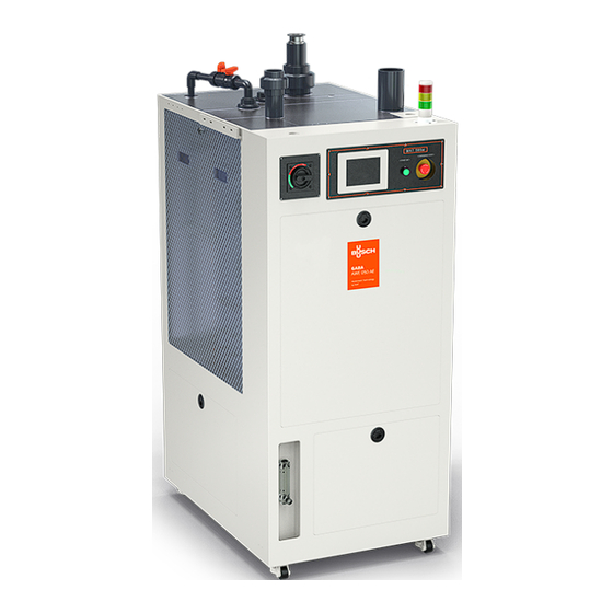
2 | Before Use Product Description Product Front Description Gas Outlets Gas Inlets Touch Screen Main Power Breaker Cabinet Exhaust Tower Lamp Emergency Switch Start Switch Flowmeters Fig 1.1 Name of Product Front 6 | 40 Instruction Manual GABA AWE 050 AE_EN_en... - Page 7 Before Use | 2 Internal Product Description Inlet Preventer Wet Tank Pump Fig 1.2 Name of the Internal Product Instruction Manual GABA AWE 050 AE_EN_en 7 | 40...
-
Page 8: Related To Safety
3 | Related to Safety Related to Safety Safety Equipment WARNING Wearing inappropriate safety equipment or not wearing any may cause fatal damages to the body. Symbol Meaning of the Symbol You must wear safety gloves in areas indicated with this symbol. Wear safety gloves appropriate to the work. -
Page 9: Risk Factors
Related to Safety | 3 Risk Factors WARNING Be sure to work after wearing appropriate protective equipment when implementing any work attached with a hazard label. If it is not observed, it may cause fatal damages to the body. Risk Label Meaning of the Symbol - You may be electrocuted when contacted or approached. -
Page 10: Safety Label
3 | Related to Safety Risk Label Meaning of the Symbol - Substances such as harmful dust, vapor, and gas may occur and damage the respiratory system. Protective Equip- ment Noxious Gas Expo- sure Wear safety glasses, safety gloves, safety shoes, and gas mask. -
Page 11: Precautions
Related to Safety | 3 Precautions Pressure - during normal operation WARNING This product uses the utilities such as water, nitrogen gas, and compressed dry air with high pressure. When inappropriate operation method is used, the user’s body may be exposed to high pressured gas. - Page 12 3 | Related to Safety Gas – during Normal Operation WARNING This product may flow harmful gases according to the installed environment. Users may be exposed to harmful gases. ● Before suspending the operation, inform the person interested such as product users and facility managers of operation suspension and the reasons for operation suspension.
-
Page 13: Interlock
Related to Safety | 3 Contaminant – during Maintenance CAUTION If inspection, maintenance, and repair work are necessary, please observe the following direc- tions to prevent danger. ● The facility manager of the facility installed with this product must process and discharge con- taminants produced by this product in accordance with laws and regulations. -
Page 14: Emergency Stop
3 | Related to Safety System Error / Supply Water Circulation Drain Pump 3-Way Valve (Op- Output Pump tion) Supply Water By-pass Flow Error Circulation Flow By-pass Low Error Circulation Flow By-pass High Error Circulation Pump By-pass Trip Water Leak By-pass Inlet Pressure By-pass... - Page 15 Related to Safety | 3 System Recovery WARNING Do not insert process gases to the product until the product or the surrounding environment of the product become a normal status. Gas leakage may cause fatal damages to the user’s body. ●...
-
Page 16: Facility Requirements
4 | Facility Requirements Facility Requirements Installation Environment CAUTION This product is designed to be installed indoors where there is no risk of explosion. Install at an appropriate installation environment for normal operation and maintenance. Table 3.1 Required Environment for Installation Classification Required Environment Temperature... -
Page 17: Utility
Facility Requirements | 4 Fig 3.1 Required Spaces for Installation Description 1,729 1,100 Utility Table 3.3 Utility Classification Specifications Power Main Pow- 220V, 50Hz, 20KA Power Consumption 4,5KW MAX @PF 0.98 SCCR: 1.5KA Cir. Pump 1500W Drain 260W Pump N2 Gas 4 ⁓... -
Page 18: Loto Location And Measures Time
4 | Facility Requirements Classification Specifications Drain – Natural drain: 40A (1-1/2’’) PVC Union, Acid drain – Natural drain: 20A (3/4’’) PVC Union, Acid drain (Option) LOTO Location and Measures Time Fig 3.2 LOTO Location Description N₂ IN Water IN ●... -
Page 19: Installation
Installation | 5 Installation Product Transport Description Label Left ● For facility transport, turn the wheels attached to the facility to float it from the ground and move it to the right position. ● When transporting, it should be floated less than 1cm to prevent damage of the top part of the facility. -
Page 20: Utility Installation
5 | Installation Utility Installation Fig 4.2 Connection Parts of the Product Utility Description Gas Inlet : Gas Inlet Gas Exhaust: Final Gas Exhaust Cabinet Exhaust: Cabinet Temperature Drain Pipe: Waste Water Exhaust within Increase Prevention the Product Water Supply Pipe: Supply Water within N2 Supply Pipe: Supply N2 within the the Product Product... -
Page 21: Installation Inspection
Installation | 5 Bypass pipe connection (when adding Bypass option) ● Connect the Bypass pipe to the product. ● Connect suing a NW50 Size pipe. ● Connect using an appropriate Gasket and Clamp. Gas inlet pipe connection ● Connect the bypass pipe to the product. ●... - Page 22 5 | Installation ● Check the connection state of each pipe. ● Check the pressure and flow rate supplied to each pipe. ● Pressure may vary according to the subject of supply (installation environment). Flow rate may be checked by adjusting the Flowmeter. Power Line Inspection WARNING Be sure to work after turning OFF the main power.
-
Page 23: Operation
Operation | 6 Operation Start WARNING Inappropriate system operation during normal operation my cause fatal damages not only to this product but also to other connected products. If it is not appropriate to normal operation, do not operate until it becomes an appropriate environment. Make sure to work after check- ing the manual when operating. -
Page 24: Set Up Mode
6 | Operation Set Up Mode ● After set up or when changing the setting during operation, you can change the set values relat- ed to the alarm or the boundary values of the warning, and other operation in the Set Up Mode. Fig 5.2 Set Up Mode Screen ERROR HISTORY ●... -
Page 25: Manual Mode
Operation | 6 Manual Mode MANUAL MODE ● Select the MANUAL MODE at the menu of the main screen or if you select MODE CHANGE at AU- TO MODE, Manual operation is possible. ● In Manual Mode, all devices and utilities can be selected and controlled independently on the Touch Screen. -
Page 26: Other Modes
6 | Operation Fig 5.5 AUTO MODE Screen Other Modes POWER SAVING MODE ● If there is no touch entry for 10 minutes, the backlight power of the touchscreen is shut off. ● If the backlight power is shut off, the screen turns on if you touch the screen. DATA LOG ●... -
Page 27: Setting Mode (Other Than Plc)
Operation | 6 Setting mode (other than PLC) Digital Pressure Gauge (PSQ) ● May be set according to the fluid pressure of Water and Air. Alarm Value Setting 1. PV Indicator (Green, Red, Orange Color): Operation Mode: PV (Current Value). 2. -
Page 28: Trouble Shooting
7 | Trouble Shooting Trouble Shooting Tower Lamp ● It flashes in different colors so that it is easy for users to understand according to the operation state of the product. Lamp System Condition Green Steady When the system is normal in the automatic & manual mode. Yellow Steady When the system is in the initial screen. - Page 29 Trouble Shooting | 7 Supply Water Flow Error Alarm occurrence Step 1 Check Replace and Resume normal operation repair process of valve Step 2 Check Normal Replace and Reset the pressure operation repair gauge Step 3 Check the Replace and Next normal operation of the supply...
- Page 30 7 | Trouble Shooting Circulation Pump Trip Error Alarm occurrence Step 1 Check Replace and Resume the alarm default repair process value Step 2 Check Normal Reset Reset normal opeation operation of EOCR Step 3 Check the Replace and Next normal operation of repair the circulation...
- Page 31 Trouble Shooting | 7 Main Tank Level Error (Low, High, H-High) Alarm occurrence Step 1 Check for leaks. Supply water Resume set recommended pipe inspection supply and circulation process water flow rates Step 2 Normal Water level, Replace Reset sensor comparison operation and repair inspection...
- Page 32 7 | Trouble Shooting Exhaust Pressure Error Alarm occurrence Step 1 Check Resume Reset alarm default process Step 2 Pressure Normal Zero Reset sensor zero operation adjustment check Step 3 Exhaust Next Pipe sampling pipe cleaning step check Step 4 Pipe Exhaust pipe blockage...
- Page 33 Trouble Shooting | 7 Level Sensor Error Alarm occurrence Step 1 Level sensor Replace and Resume power check repair process Step 2 Normal Normal Replace and Reset operation check of operation repair level sensor Step 3 Sensor pipe Pipe Next clogging check cleaning step...
-
Page 34: Maintenance
8 | Maintenance Maintenance Preparation Materials Protective Equipment ● Refer to Chapter 2.1 Protective Equipment Working Tools Name Role ● Tighten and loosen bolt. ● Required Size: 1/4″, 3/8’’, 13 mm. ● Required Quantity: each more than 1 for each. Spanner ●... -
Page 35: Equipement Stop
Maintenance | 8 Equipement Stop WARNING Before stopping the equipment, shut off the flow of process gases. If not shutoff, process gases may be leaked and they may cause fatal injuries to the users. ● 5.5 Safely stop the equipment according to the method specified in the cooling methods. Module Replacement Inlet ●... -
Page 36: Preventive Maintenance
8 | Maintenance Nozzle ● To clean the module, prepare safety equipment specified in chapter 2.1 and wear appropriate protective equipment. ● Prepare the working tools specified in chapter 7.1. ● The cleaning sequence of nozzles is as follows. ● Separate the view cover attached to the chamber. ●... -
Page 37: Eu Declaration Of Conformity
EU Declaration of Conformity This Declaration of Conformity and the CE-markings affixed to the nameplate are valid for the machine within the Busch scope of delivery. This Decla- ration of Conformity is issued under the sole responsibility of the manufacturer. - Page 38 Notes Notes 38 | 40 Instruction Manual GABA AWE 050 AE_EN_en...
- Page 39 N otes Instruction Manual GABA AWE 050 AE_EN_en 39 | 40...
- Page 40 With a network of over 60 companies in more than 40 countries and agencies worldwide, Busch has a global presence. In every country, highly competent local personnel delivers custom-tailored support backed by a global network of expertise. Wherever you are.
Need help?
Do you have a question about the GABA AWE 050 AE and is the answer not in the manual?
Questions and answers