Table of Contents
Advertisement
Quick Links
PRODUCT NAME
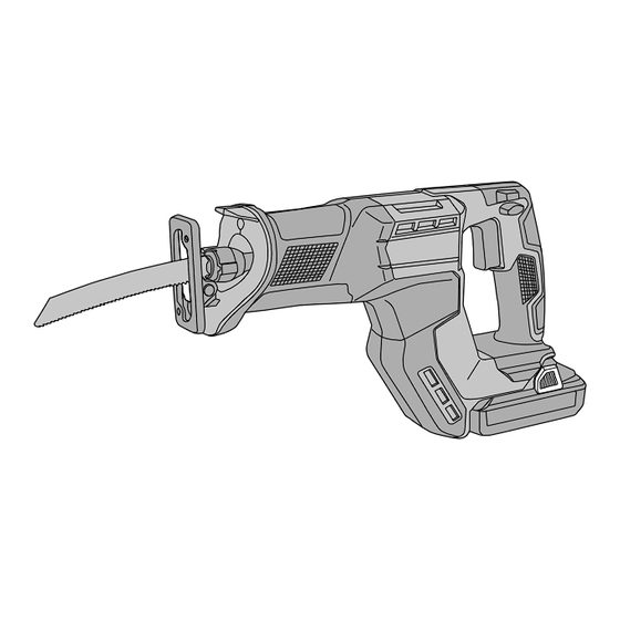
18 V Cordless Reciprocating Saw
CR 18DMA
Model
CONTENTS
REPAIR GUIDE ----------------------------------------------------------------------------------------------------------------- 1
1. Precautions on disassembly and reassembly ----------------------------------------------------------- 1
• Disassembly -------------------------------------------------------------------------------------------------- 1
• Reassembly -------------------------------------------------------------------------------------------------- 5
• Application of lubricant ------------------------------------------------------------------------------------- 7
• Tightening torque ------------------------------------------------------------------------------------------- 8
• Checking after reassembly ------------------------------------------------------------------------------- 8
• No-load current value -------------------------------------------------------------------------------------- 8
• Connecting diagram ---------------------------------------------------------------------------------------- 9
CONFIDENTIAL
Overseas Sales Management Dept.
Apr. 2023
C
Page
Advertisement
Table of Contents

Related Manuals for Koki Holdings CR 18DMA

Summary of Contents for Koki Holdings CR 18DMA
-
Page 1: Table Of Contents
CONFIDENTIAL Apr. 2023 PRODUCT NAME 18 V Cordless Reciprocating Saw CR 18DMA Model CONTENTS Page REPAIR GUIDE ----------------------------------------------------------------------------------------------------------------- 1 1. Precautions on disassembly and reassembly ----------------------------------------------------------- 1 • Disassembly -------------------------------------------------------------------------------------------------- 1 • Reassembly -------------------------------------------------------------------------------------------------- 5 • Application of lubricant ------------------------------------------------------------------------------------- 7 •... -
Page 2: Repair Guide
1. Precautions on disassembly and reassembly [Bold] numbers in the description below correspond to the item numbers in the parts list and exploded assembly diagram for the Model CR 18DMA. Disassembly First, be sure to remove the saw blade from the main body to prevent damage to the cutting edges of the saw blade and avoid personal injury due to the saw blade. - Page 3 2. Removal of the base Loosen the Hex. Socket Hd. Bolt (W/Flange) M5 x 8 [28] and Hex. Socket Bolt M5 [1] and remove the Base Plate [27] and Base [26] from the gear cover ass’y. • Removal of the base Gear cover ass’y [46] [47]...
- Page 4 4. Disassembly of the blade holder section (1) Remove the Spiral Retaining Ring D16 [14] from the groove of the Sleeve [17] by raising the end of the Spiral Retaining Ring D16 [14] with a small flat-blade screwdriver as shown in the following figure A. (2) Insert a small flat-blade screwdriver and push it up as shown in figure B to remove the Blade Holder [15] from the inside of the Blade Holder Cover [20].
- Page 5 5. Removal of the gear (1) Loosen the six Hex. Socket Bolts M5 [1] and remove the Upper Cover [2]. (2) Remove the Counter Weight [38] together with Sleeve (B) [7] and two Steel Balls D4.76 [6]. (3) Remove the four Steel Balls D4.76 [6], two Weight Guides [5] , two Weight Dampers [4], and two Spacers [8].
-
Page 6: Reassembly
Reassembly Reassembly can be accomplished by following the disassembly procedures in reverse. However, special attention should be given to the following items. 1. Mounting the counter weight (1) Position the four Steel Balls D4.76 [6] properly so that they are fitted in the concave portions of the Counter Weight [38] as shown in the figure below. - Page 7 2. Wiring of the power supply unit (1) Connect the internal wires correctly according to the connecting diagram shown on page 9. (2) Be sure to mount each part and each internal wire to the correct positions, and be careful not to get any internal wire caught at the time of reassembly.
-
Page 8: Application Of Lubricant
Application of lubricant Apply specified amount of Cosmo Grease KMC No. 1 to the following portions. Amount Area Application area of grease Outer circumference of the Steel Ball 0.3 g D4.76 [6] in total (B) Outer circumference of the gear shaft 0.3 g (C) Inner circumference of the Gear [40] 0.5 g... -
Page 9: Tightening Torque
Tightening torque Tightening torque Item Part name N•m kgf•cm Hex. Socket Bolt M5 5.9 ± 1.5 60 ± 15 [10] Low Head Hex. Socket Bolt M4 x 8 4.4 ± 0.5 45 ± 5 [28] Hex. Socket Hd. Bolt (W/Flange) M5 x 8 5.9 ±... -
Page 10: Connecting Diagram
Connecting diagram [46] [49] [47] Speed Control Switch [46] Black Connector White Connector Yellow White Connector Blue Black Stator Controller Ass’y [47] White Stator PCB Blue Black Blue Gray Yellow Black (1 pc.): 9 White (7 pcs.): 1 to 7 Black Battery Terminal [49] Indicator PCB ass’y...
Need help?
Do you have a question about the CR 18DMA and is the answer not in the manual?
Questions and answers