Table of Contents
Advertisement
Quick Links
Copyright Notice:
Copyright Notice:
Copyright Notice:
Copyright Notice:
Copyright Notice:
No part of this installation guide may be reproduced, transcribed, transmitted, or trans-
lated in any language, in any form or by any means, except duplication of documen-
tation by the purchaser for backup purpose, without written consent of ASRock Inc.
Products and corporate names appearing in this guide may or may not be registered
trademarks or copyrights of their respective companies, and are used only for identifica-
tion or explanation and to the owners' benefit, without intent to infringe.
Disclaimer:
Disclaimer:
Disclaimer:
Disclaimer:
Disclaimer:
Specifications and information contained in this guide are furnished for informational
use only and subject to change without notice, and should not be constructed as a
commitment by ASRock. ASRock assumes no responsibility for any errors or omissions
that may appear in this guide.
With respect to the contents of this guide, ASRock does not provide warranty of any kind,
either expressed or implied, including but not limited to the implied warranties or
conditions of merchantability or fitness for a particular purpose. In no event shall
ASRock, its directors, officers, employees, or agents be liable for any indirect, special,
incidental, or consequential damages (including damages for loss of profits, loss of
business, loss of data, interruption of business and the like), even if ASRock has been
advised of the possibility of such damages arising from any defect or error in the guide
or product.
This device complies with Part 15 of the FCC Rules. Operation is subject to the
following two conditions:
(1) this device may not cause harmful interference, and
(2) this device must accept any interference received, including interference that
may cause undesired operation.
CALIFORNIA, USA ONLY
The Lithium battery adopted on this motherboard contains Perchlorate, a toxic
substance controlled in Perchlorate Best Management Practices (BMP) regulations
passed by the California Legislature. When you discard the Lithium battery in
California, USA, please follow the related regulations in advance.
"Perchlorate Material-special handling may apply, see
www.dtsc.ca.gov/hazardouswaste/perchlorate"
ASRock Website: http://www.asrock.com
Copyright©2008 ASRock INC. All rights reserved.
ASRock
Published September 2008
N61P-GS / N61P-S
Motherboard
1 1 1 1 1
Advertisement
Table of Contents

Related Manuals for ASROCK N61P-GS


Summary of Contents for ASROCK N61P-GS
- Page 1 ASRock. ASRock assumes no responsibility for any errors or omissions that may appear in this guide. With respect to the contents of this guide, ASRock does not provide warranty of any kind, either expressed or implied, including but not limited to the implied warranties or conditions of merchantability or fitness for a particular purpose.
-
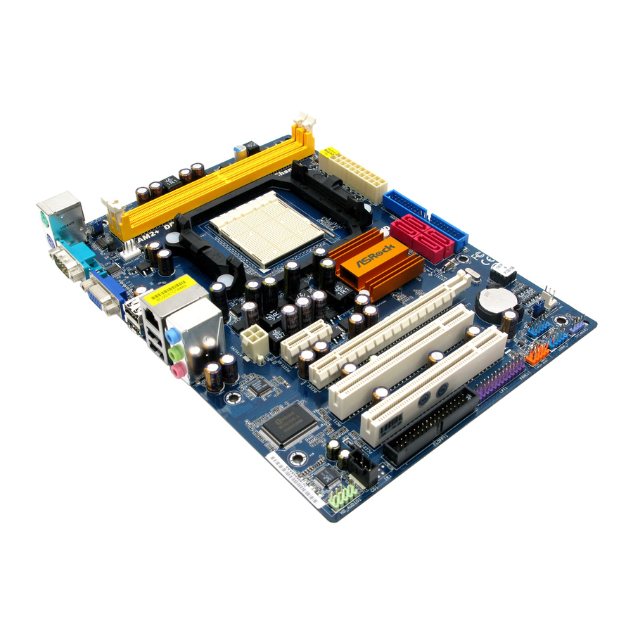
Page 2: Motherboard Layout
Motherboard Layout PS2_USB_PW1 Jumper Chassis Speaker Header CPU Fan Connector (CPU_FAN1) (SPEAKER 1, Purple) 2 x 240-pin DDR2 DIMM Slots USB 2.0 Header (USB6_7, Blue) (Dual Channel: DDRII_1, DDRII_2; Yellow) System Panel Header (PANEL1, Orange) ATX Power Connector (ATXPWR1) Print Port Header (LPT1, Purple) -
Page 3: Speed Led
Microphone (Pink) PS/2 Keyboard Port (Purple) * On N61P-GS motherboard, there are two LED next to the LAN port. Please refer to the table below for the LAN port LED indications. N61P-S motherboard does not have LAN port LED. LAN Port LED Indications... - Page 4 ASRock’s commitment to quality and endurance. In this manual, chapter 1 and 2 contain introduction of the motherboard and step-by-step guide to the hardware installation. Chapter 3 and 4 contain the configuration guide to BIOS setup and information of the Support CD.
-
Page 5: Specifications
- Micro ATX Form Factor: 9.6-in x 7.0-in, 24.4 cm x 17.8 cm - Support for Socket AM2+ / AM2 processors: AMD Phenom FX / Phenom / Athlon 64 FX / Athlon 64 X2 Dual-Core / Athlon X2 Dual-Core / Athlon 64 / Sempron processor (see CAUTION 1) - Supports AMD’s Cool ‘n’... - Page 6 Connector - 4 x Serial ATAII 3.0Gb/s connectors, support RAID (RAID 0, RAID 1, RAID 0+1, RAID 5, JBOD), NCQ and “Hot Plug” functions (see CAUTION 7) - 1 x ATA133 IDE connector (supports 2 x IDE devices) - 1 x Floppy connector...
- Page 7 Before installing SATAII hard disk to SATAII connector, please read the “SATAII Hard Disk Setup Guide” on page 22 of “User Manual” in the support CD to adjust your SATAII hard disk drive to SATAII mode. You can also connect SATA hard disk to SATAII connector directly.
- Page 8 13. This motherboard supports ASRock AM2 Boost overclocking technology. If you enable this function in the BIOS setup, the memory performance will improve up to 12.5%, but the effect still depends on the AM2 CPU you adopt. Enabling this function will overclock the chipset/CPU reference clock.
-
Page 9: Pre-Installation Precautions
Installation Installation Installation This is a Micro ATX form factor (9.6-in x 7.0-in, 24.4 cm x 17.8 cm) motherboard. Before you install the motherboard, study the configuration of your chassis to en- sure that the motherboard fits into it. Pre-installation Precautions... -
Page 10: Installation Of Cpu Fan And Heatsink
Step 4. When the CPU is in place, press it firmly on the socket while you push down the socket lever to secure the CPU. The lever clicks on the side tab to indicate that it is locked. -
Page 11: Installing A Dimm
Unlock a DIMM slot by pressing the retaining clips outward. Step 2. Align a DIMM on the slot such that the notch on the DIMM matches the break on the slot. The DIMM only fits in one correct orientation. It will cause permanent damage to the motherboard and the DIMM if you force the DIMM into the slot at incorrect orientation. -
Page 12: Expansion Slots (Pci And Pci Express Slots)
PCI slots: PCI slots are used to install expansion cards that have the 32-bit PCI interface. PCIE slots: PCIE1 (PCIE x1 slot) is used for PCI Express cards with x1 lane width cards, such as Gigabit LAN card, SATA2 card, etc. -
Page 13: Jumpers Setup
CLRCMOS1 for 5 seconds. However, please do not clear the CMOS right after you update the BIOS. If you need to clear the CMOS when you just finish updating the BIOS, you must boot up the system first, and then shut it down before you do the clear-CMOS action. -
Page 14: Onboard Headers And Connectors
Floppy Connector (33-pin FLOPPY1) (see p.2 No. 19) the red-striped side to Pin1 Note: Make sure the red-striped side of the cable is plugged into Pin1 side of the connector. Primary IDE connector (Blue) (39-pin IDE1, see p.2 No. 6) - Page 15 HDA to function correctly. Please follow the instruction in our manual and chassis manual to install your system. 2. If you use AC’97 audio panel, please install it to the front panel audio header as below: A.
- Page 16 For Windows 2000 / XP / XP 64-bit OS: Please select “Front Mic” as default record device. If you want to hear your voice through front mic, please deselect "Mute" icon in “Front Mic” of “Playback” portion. For Windows ®...
-
Page 17: Installing Windows / Vista
Vista 64-bit on your SATA / SATAII HDDs without RAID functions, you don’t have to make a SATA / SATAII driver diskette. Besides, there is no need for you to change the BIOS setting. You can start to install Windows ®... -
Page 18: Bios Information
Untied Overclocking function, please enter “Overclock Mode” option of BIOS setup to set the selection from [Auto] to [CPU, PCIE, Async.]. Therefore, CPU FSB is untied during overclocking, but PCI / PCIE buses are in the fixed mode so that FSB can operate under a more stable overclocking environment. - Page 19 1. Einführung 1. Einführung 1. Einführung Wir danken Ihnen für den Kauf des ASRock N61P-GS / N61P-S Motherboard, ein zuverlässiges Produkt, welches unter den ständigen, strengen Qualitätskontrollen von ASRock gefertigt wurde. Es bietet Ihnen exzellente Leistung und robustes Design, gemäß...
-
Page 20: Spezifikationen
1 . 2 Spezifikationen Spezifikationen Plattform - Micro ATX-Formfaktor: 24.4 cm x 17.8 cm; 9.6 Zoll x 7.0 Zoll - Unterstützung für Socket AM2+ / AM2-Prozessoren: AMD Phenom FX / Phenom / Athlon 64 FX / Athlon 64 X2 Dualkern... - Page 21 Anschlüsse - 4 x SATAII-Anschlüsse, unterstützt bis 3.0 Gb/s Datenübertragungsrate, unterstützt RAID (RAID 0, RAID 1, RAID 0+1, RAID 5, JBOD), NCQ und “Hot Plug” Funktionen (siehe VORSICHT 7) - 1 x ATA133 IDE-Anschlüsse (Unterstützt bis 2 IDE-Geräte) - 1 x FDD-Anschlüsse - 1 x Druckerport-Anschlussleiste - CPU/Gehäuse-Lüfteranschluss...
- Page 22 Beachten Sie bitte, dass Overclocking, einschließlich der Einstellung im BIOS, Anwenden der Untied Overclocking-Technologie oder Verwenden von Overclocking-Werkzeugen von Dritten, mit einem gewissen Risiko behaftet ist. Overclocking kann sich nachteilig auf die Stabilität Ihres Systems auswirken oder sogar Komponenten und Geräte Ihres Systems beschädigen.
- Page 23 CPU-Busfrequenzen abweichen, können Instabilität des Systems verursachen oder die CPU beschädigen. 12. Wird eine Überhitzung der CPU registriert, führt das System einen automatischen Shutdown durch. Bevor Sie das System neu starten, prüfen Sie bitte, ob der CPU-Lüfter am Motherboard richtig funktioniert, und stecken Sie bitte den Stromkabelstecker aus und dann wieder ein.
-
Page 24: Einstellung Der Jumper
+5VSB (Standby) zu setzen (siehe S.2, No. 1) und die PS/2 oder USB- Weckfunktionen zu aktivieren. Hinweis: Um +5VSB nutzen zu können, muss das Netzteil auf dieser Leitung 2A oder mehr leisten können. CMOS löschen (CLRCMOS1, 3-Pin jumper) (siehe S.2, No. 13) - Page 25 (33-Pin FLOPPY1) die rotgestreifte Seite auf Stift 1 (siehe S.2, No. 19) Hinweis: Achten Sie darauf, dass die rotgestreifte Seite des Kabel mit der Stift 1- Seite des Anschlusses verbunden wird. Primärer IDE-Anschluss (blau) (39-pin IDE1, siehe S.2, No. 6)
- Page 26 Interne Audio-Anschlüsse Diese ermöglichen Ihnen Stereo-Signalquellen, wie z. B. CD-L (4-Pin CD1) CD-ROM, DVD-ROM, TV-Tuner (CD1: siehe S.2 - No. 20) CD-R oder MPEG-Karten mit Ihrem System zu verbinden. Anschluss für Audio auf Dieses Interface zu einem der Gehäusevorderseite Audio-Panel auf der Vorderseite Ihres Gehäuses, ermöglicht...
- Page 27 E. Rufen Sie das BIOS-Setup-Dienstprogramm auf. Wechseln Sie zu Erweiterte Einstellungen und wählen Sie Chipset-Konfiguration. Setzen Sie die Option Frontleistenkontrolle von [Automatisch] auf [Aktiviert]. F. Rufen Sie das Windows-System auf. Klicken Sie auf das Symbol in der Taskleiste unten rechts, um den Realtek HD Audio-Manager aufzurufen. ®...
- Page 28 Obwohl dieses Motherboard einen 24-pol. ATX-Stromanschluss bietet, kann es auch mit einem modifizierten traditionellen 20-pol. ATX-Netzteil verwendet werden. Um ein 20-pol. ATX-Netzteil zu verwenden, stecken Sie den Stecker mit Pin 1 und Pin 13 ein. Installation eines 20-pol. ATX-Netzteils Anschluss für...
- Page 29 Dieses Motherboard unterstützt eine Reiche von Microsoft ® Windows ® Betriebssystemen: 2000 / XP / XP Media Center / XP 64-Bit / Vista / Vista Bit. Die Ihrem Motherboard beigefügte Support-CD enthält hilfreiche Software, eren Treiber und Hilfsprogramme, mit denen Sie die Funktionen Ihres Motherboards verbessern können Legen Sie die Support-CD zunächst in Ihr CD-ROM-Laufwerk...
-
Page 30: Contenu Du Paquet
Contenu du paquet Contenu du paquet Carte mère ASRock N61P-GS / N61P-S (Facteur de forme Micro ATX: 9.6 pouces x 7.0 pouces, 24.4 cm x 17.8 cm) Guide d’installation rapide ASRock N61P-GS / N61P-S CD de soutien ASRock N61P-GS / N61P-S Un câble ruban IDE Ultra ATA 66/100/133 80 conducteurs (Optionnelle) - Page 31 9.6 pouces x 7.0 pouces, 24.4 cm x 17.8 cm - Prise en charge des processeurs Socket AM2+ / AM2: AMD Phenom FX / Phenom / Athlon 64 FX / Athlon 64 X2 Dual-Core / Athlon X2 Dual-Core / Athlon 64 / processeur Sempron (voir ATTENTION 1) - Supporte la technologie Cool ‘n’...
- Page 32 - br. 24 connecteur d’alimentation ATX - br. 4 connecteur d’alimentation 12V ATX - Connecteurs audio internes - Connecteur audio panneau avant - 2 x En-tête USB 2.0 (prendre en charge 4 ports USB 2.0 supplémentaires) (voir ATTENTION 8) BIOS - 4Mb BIOS AMI - BIOS AMI - Support du “Plug and Play”...
- Page 33 / Vista 64-bit Certifications - FCC, CE * Pour de plus amples informations sur les produits, s’il vous plaît visitez notre site web: http://www.asrock.com ATTENTION Il est important que vous réalisiez qu’il y a un certain risque à effectuer l’overclocking, y compris ajuster les réglages du BIOS, appliquer la technologie Untied Overclocking, ou...
- Page 34 Intelligent Energy Saver (L’économiseur d’énergie intelligent). Site Web d’ASRock: http://www.asrock.com 11. Même si cette carte mère offre un contrôle sans souci, il n’est pas recommandé d’y appliquer un over clocking. Les fréquences autres que les fréquences de bus d’UC recommandées risquent de déstabiliser le système ou d’endommager l’UC.
- Page 35 « FERME ». Si aucun capuchon n e r e l i e l e s b r o c h e s , l e c a v a l i e r e s t «...
- Page 36 (FLOPPY1 br. 33) le côté avec fil rouge côté Broche1 (voir p.2 fig. 19) Note: Assurez-vous que le côté avec fil rouge du câble est bien branché sur le côté Broche1 du connecteur. Connecteur IDE primaire (bleu) (IDE1 br. 39, voir p.2 No. 6)
- Page 37 En-tête USB 2.0 A côté des quatre ports USB 2.0 par défaut sur le panneau (USB6_7 br.9) E/S, il y a deux embases USB (voir p.2 No. 16) 2.0 sur cette carte mère. Chaque embase USB 2.0 peut (USB4_5 br.9) prendre en charge 2 ports USB (voir p.2 No.
- Page 38 1. L’audio à haute définition (HDA) prend en charge la détection de fiche, mais le fil de panneau sur le châssis doit prendre en charge le HDA pour fonctionner correctement. Veuillez suivre les instructions dans notre manuel et le manuel de châssis afin installer votre système.
- Page 39 (voir p.2 fig. 2) ien que cette carte mère offre un support de (Ventilateur silencieux) ventilateur de CPU à 4 broches , le ventilateur de CPU à 3 broches peut bien fonctionner même sans la fonction de commande de vitesse du ventilateur.
-
Page 40: Informations Sur Le Cd De Support
BIOS après le POST, veuillez redémarrer le système en pressant <Ctl> + <Alt> + <Suppr>, ou en pressant le bouton de reset sur le boîtier du système. Vous pouvez également redémarrer en éteignant le système et en le rallumant. - Page 41 Questa Guida Rapida all’Installazione contiene l’introduzione alla motherboard e la guida passo-passo all’installazione. Informazioni più dettagliate sulla motherboard si possono trovare nel manuale per l’utente presente nel CD di supporto. Le specifiche della scheda madre e il software del BIOS possono essere aggiornati, pertanto il contenuto di questo manuale può...
- Page 42 - Micro ATX Form Factor: 9.6-in x 7.0-in, 24.4 cm x 17.8 cm Processore - Supporto per processori Socket AM2+ / AM2: AMD Phenom FX / Phenom / Athlon 64 FX / Athlon 64 X2 Dual-Core / Athlon X2 Dual-Core / Athlon 64 / processore Sempron (vedi ATTENZIONE 1) - Supporto tecnologia AMD Cool ‘n’...
- Page 43 - Connettore HD Audio: ingresso linea / cassa frontale / microfono Connettori - 4 x connettori SATAII 3.0Go/s, sopporta RAID (RAID 0, RAID 1, RAID 0+1, RAID 5, JBOD), NCQ e “Collegamento a caldo” (vedi ATTENZIONE 7) - 1 x connettori ATA133 IDE (supporta fino a 2 dispositivi IDE)
- Page 44 * Per ulteriori informazioni, prego visitare il nostro sito internet: http://www.asrock.com AVVISO Si prega di prendere atto che la procedura di overclocking implica dei rischi, come anche la regolazione delle impostazioni del BIOS, l’applicazione della tecnologia Untied Overclocking Technology, oppure l’uso di strumenti di overclocking forniti da terzi. L’overclocking può...
- Page 45 è una tecnologia rivoluzionaria che consente di realizzare risparmi energetici senza pari. Il regolatore di tensione è in grado di ridurre il numero di fasi in uscita in modo da migliorare l’efficienza quando i nuclei della CPU sono inattivi. In alter parole, permette di realizzare risparmi energetica senza pari e di migliorare l’efficienza energetica senza ridurre le prestazioni del...
- Page 46 Quando il ponticello è posizionato sui pin, il jumper è “CORTOCIRCUITATO”. Se sui pin non ci sono ponticelli, il jumper è “APERTO”. L’illustrazione mostra un jumper a 3 pin in cui il pin1 e il pin2 sono “CORTOCIRCUITATI” quando il ponticello è CORTOCIRCUITATO APERTO posizionato su questi pin.
- Page 47 (33-pin FLOPPY1) (vedi p.2 item 19) Lato del Pin1 con la striscia rossa Nota: Assicurarsi che il lato del cavo con la striscia rossa sia inserito nel lato Pin1 del connettore. Connettore IDE primario (blu) (39-pin IDE1, vedi p.2 Nr. 6)
- Page 48 Connettere al gruppo alimentazione SATA al di alimentazione connettore power dell’alimentatore. Collettore USB 2.0 Oltre alle quattro porte USB 2.0 predefinite nel pannello I/O, la (9-pin USB6_7) scheda madre dispone di due (vedi p.2 No. 16) intestazioni USB 2.0. Ciascuna intestazione USB 2.0 supporta...
- Page 49 1. La caratteristica HDA (High Definition Audio) supporta il rilevamento dei connettori, però il pannello dei cavi sul telaio deve supportare la funzione HDA (High Definition Audio) per far sì che questa operi in modo corretto. Attenersi alle istruzioni del nostro manuale e del manuale del telaio per installare il sistema.
- Page 50 Sebbene la presente scheda madre disponga di un supporto per ventola CPU a 4 piedini (ventola silenziosa), la ventola CPU a 3 piedini è in grado di funzionare anche senza la funzione di controllo della velocità della ventola. Se si intende collegare la ventola CPU a 3 piedini al connettore della ventola CPU su questa scheda madre, collegarla ai piedini 1-3.
- Page 51 BIOS; altrimenti, POST continua con i suoi test di routine. Per entrare il BIOS Setup dopo il POST, riavvia il sistema premendo <Ctl> + <Alt> + <Delete>, o premi il tasto di reset sullo chassis del sistema. El BIOS Setup Utility es diseñádo “user-friendly”.
-
Page 52: Contenido De La Caja
ASRock. Esta Guía rápida de instalación contiene una introducción a la placa base y una guía de instalación paso a paso. Puede encontrar una información más detallada sobre la placa base en el manual de usuario incluido en el CD de soporte. - Page 53 1 . 2 1 . 2 Especificación Plataforma - Factor forma Micro ATX: 24,4 cm x 17,8 cm, 9,6” x 7,0” Procesador - Soporte para procesadores con zócalo AM2+ y AM2: AMD Phenom FX, Phenom, Athlon 64 FX, Athlon 64 X2 Dual-Core, Athlon X2 Dual-Core, Athlon 64 y procesador Sempron (vea ATENCIÓN 1)
- Page 54 - 1 x Puerto LAN RJ-45 con LED (LED de ACCIÓN/ENLACE y LED de VELOCIDAD) (N61P-GS) - 1 x Puerto LAN RJ-45 (N61P-S) - Conexión de HD audio: Entrada de línea / Altavoz frontal / Micrófono Conectores - 4 x conexiones SATAII, admiten una velocidad de transferencia de datos de hasta 3,0Gb/s, soporta RAID (RAID 0, RAID 1, RAID 0+1, RAID 5, JBOD), NCQ y “Conexión...
- Page 55 ADVERTENCIA Tenga en cuenta que hay un cierto riesgo implícito en las operaciones de aumento de la velocidad del reloj, incluido el ajuste del BIOS, aplicando la tecnología de aumento de velocidad liberada o utilizando las herramientas de aumento de velocidad de otros fabricantes.
- Page 56 Antes de instalar un disco duro SATAII en el conector SATAII, consulte la sección “Guía de instalación de discos duros SATAII” en la página 22 del “Manual de usuario” que se incluye en el CD de soporte para configurar su disco duro SATAII en modo SATAII. También puede conectar un disco duro SATA directamente al conector SATAII.
- Page 57 3 para habilitar +5VSB (vea p.2, No. 1) (standby) para PS/2 o USB wake up events. Atención: Para elegir +5VSB, se necesita corriente mas que 2 Amp proveida por la fuente de electricidad. Limpiar CMOS (CLRCMOS1, jumper de 3 pins) (ver p.2, No.
-
Page 58: Conectores
(vea p.2, No. 19) la banda roja debe quedar en el mismo lado que el contacto 1 Atención: Asegúrese que la banda roja del cable queda situado en el mismo lado que el contacto 1 de la conexión. IDE conector primario (azul) (39-pin IDE1, vea p.2, No. - Page 59 Cable de alimentación Conecte el extremo negro del de serie ATA (SATA) cable de SATA al conector de energía de la unidad. A (Opcional) Conectar a la conexión de continuación, conecte el alimentación del disco Conectar a la fuente duro SATA extremo blanco del cable de de alimentación...
- Page 60 2. Si utiliza el panel de sonido AC’97, instálelo en la cabecera de sonido del panel frontal de la siguiente manera: A. Conecte Mic_IN (MIC) a MIC2_L.
- Page 61 Si pretende enchufar el ventilador de procesador de 3 contactos en el conector del ventilador de procesador de esta placa base, conéctelo al contacto 1-3. Contacto 1-3 conectado Instalación del ventilador de 3 contactos...
- Page 62 Para iniciar la instalación, ponga el CD en el lector de CD y se desplegará el Menú Principal automáticamente si «AUTORUN» está habilitado en su computadora. Si el Menú...
- Page 63 VGA e das CPUs suportadas no site da web da ASRock. Website de ASRock http://www.asrock.com Se precisar de apoio técnico em relação a este placa-mãe, por favor visite o nosso sítio da internet para informação específica acerca do modelo que está a utilizar. www.asrock.com/support/index.asp 1.1 Este pacote contém...
- Page 64 1.2 Especificações 1.2 Especificações Plataforma - Formato Micro ATX: 9,6 pol. x 7,0 pol., 24,4 cm x 17,8 cm - Suporte para processadores Socket AM2+ / AM2: Processador AMD Phenom FX / Phenom / Athlon 64 FX / Athlon 64 X2...
- Page 65 Microfone Conectores - 4 x conectores SATAII, suporte a taxa de transferência de dados de até 3,0 Gb/s, suporte RAID (RAID 0, RAID 1, RAID 0+1, RAID 5, JBOD), NCQ e “conexão a quente” (veja o AVISO 7) - 1 x conectores ATA133 IDE (suporta até...
- Page 66 AVISO Tenha em atenção que a operação de overclocking envolve alguns riscos, nomeadamente no que diz respeito ao ajuste das definições do BIOS, à aplicação da tecnologia Untied Overclocking ou à utilização de ferramentas de overclocking de terceiros. O overclocking pode afectar a estabilidade do seu sistema ou até...
- Page 67 / XP de 64 bits / XP SP1; SP2/2000 SP4. É uma ferramenta de overclocking da ASRock fácil de utilizar que lhe permite vigiar i seu sistema via a função de monitorização de hardware e proceder ao overclock dos dispositivos de hardware para obter o melhor desempenho em ambiente Windows ®...
-
Page 68: Configuração Dos Jumpers
(veja a folha 2, No. 1) para PS/2 ou eventos de wake up na USB. Nota: Para escolher +5VSB, é preciso uma corrente de stand by de 2 A ou mais. Restaurar CMOS (CLRCMOS1, jumper de 2 pinos) (veja a folha 2, No. 13) Configuração-padrão... - Page 69 (FLOPPY 1, 33 pinos) (veja a folha 2, No. 19) o lado com listras vermelhas para o Pino 1 Nota: Certifique-se de que o lado com listras vermelhas no cabo seja conectado ao lado Pino 1 do conector. Conector primário (Azul) (IDE1 de 39 pinos, veja a folha 2, No.
- Page 70 Estes conectores permitem CD-L que se receba entrada de (CD1 de 4 pinos) áudio em estéreo de fontes (CD1: veja a floha 2, No. 20) CD-R de áudio como CD-ROM, DVD-ROM, placa sintonizadora de TV ou placa MPEG. Conector Áudio do painel Esta é...
- Page 71 Siga s instruções que aparecem no manual e no manual do chassis para instalar o sistema. 2. Se utilizar o painel de áudio AC’97, instale-o no cabeçalho de áudio do painel frontal, como a figura abaixo mostra: A. Ligue o Mic_IN (MIC) ao MIC2_L.
- Page 72 (Ventoinha silenciosa), uma ventoinha de 3 pinos para CPU poderá funcionar mesmo sem a função de controlo de velocidade da ventoinha. Se pretender ligar uma ventoinha de 3 pinos para CPU ao conector de ventoinha do CPU nesta placa-mãe, por favor, ligue-a aos pinos 1-3.
- Page 73 64 bits. O CD de instalação que acompanha a placa Mãe contem: drivers e utilitários necessários para um melhor desempenho da placa Mãe. Para começar a usar o CD de instalação, introduza o CD na leitora de CD-ROM do computador. Automaticamente iniciará o menu principal, casa o “AUTORUN”...
- Page 74 ASRock N61P-GS / N61P-S Motherboard...
- Page 75 ‘ ’ ® ® ® ASRock N61P-GS / N61P-S Motherboard...
- Page 76 ® ASRock N61P-GS / N61P-S Motherboard...
- Page 77 “ ” ® ® ® ® ® “ ” “ ” ® ASRock N61P-GS / N61P-S Motherboard...
- Page 78 ASRock N61P-GS / N61P-S Motherboard...
- Page 79 “ ” “ ” “ ” “ ” ASRock N61P-GS / N61P-S Motherboard...
- Page 80 ASRock N61P-GS / N61P-S Motherboard...
- Page 81 CD-L CD-R ® ® ASRock N61P-GS / N61P-S Motherboard...
- Page 82 ® ® “ ” “ ” “ ” “ ” ® “ ” “ ” 4 3 2 1 ASRock N61P-GS / N61P-S Motherboard...
- Page 83 ASRock N61P-GS / N61P-S Motherboard...
- Page 84 “ ” “ ” ASRock N61P-GS / N61P-S Motherboard...
Need help?
Do you have a question about the N61P-GS and is the answer not in the manual?
Questions and answers