
Related Manuals for DEGREE CONTROLS S100

Summary of Contents for DEGREE CONTROLS S100
- Page 1 S100 Switch MANUAL S100 Switch User Manual This is proprietary information of Degree Controls Inc., contents are protected under US copyright laws © Degree Controls, Inc. 2024. S100 MANUAL 66900MN000-A02 Page 1 of 15...
- Page 2 Degree Controls Information © Copyright by Degree Controls, Inc. All Rights Reserved. This publication may be reproduced for use of registered users of Degree Controls, Inc. products. For all other purposes reproduction, storage or transmission in any form or by any means, electronic, mechanical, photocopying, recording or otherwise, requires prior permission of Degree Controls, Inc.
-
Page 3: Table Of Contents
Installation ....................................9 Troubleshooting ................................10 Appendix ............................... 11 Mechanical Information ..............................11 5.1.1 Switch ......................................11 5.1.2 Mounting Brackets .................................. 12 Wiring Diagrams ................................13 Timing....................................14 Degree Controls Inc. Product Warranty .................... 15 S100 MANUAL 66900MN000-A02 Page 3 of 15... -
Page 4: Information
The S100 air velocity switch is designed to monitor airflow in ducts, air handling units, and hood and laboratory exhausts to warn of airflow degradation. It is also used in industrial processes and electronics systems and enclosures. -
Page 5: Specifications
Figure 1 5-12VDC and 24VAC/DC Versions of the S100 Switch are Available. Specifications General The S100 Switch monitors airflow. The LED indicator lights green when there is good airflow and lights red for an alarm condition. The relay output signals an alarm condition. Item... -
Page 6: Hardware Configuration
Degree Controls to discuss available customizations for volume orders. Hardware Configuration The S100 Switch is configured to order, with choices for supply voltage and relay output alarm. The part number format is S100 – S - O, where S represents supply voltage and O represents relay output configuration. -
Page 7: Connector And Wiring Information
The S100 employs push-wire connections for fast, convenient installation. Use 20AWG to 26AWG solid core wire with a maximum insulation diameter of 1.6mm [0.06in]. Note: If you wish to connect to the S100 using wire ferrules, Phoenix Contact 3200645 is suggested. Connector Pinout... -
Page 8: Wire Insertion And Extraction
For wire insertion, push the wire with insulation 4mm [0.16in] ± 0.5mm [0.02in] through the hole in the S100 base plate until the stop face is reached. Take care to stop pushing as soon as the stop face is reached as over insertion can buckle small diameter wires. -
Page 9: Installation
For a permanent connection, a plastic adhesive may be used. The S100 is a 4-wire device, with 2 wires for power and 2 wires for the alarm output. It employs push-wire connections for fast and easy termination. -
Page 10: Troubleshooting
S100 Switch MANUAL Troubleshooting Symptom Possible Cause Corrective Action Switch does not respond, LED No power Check input voltage. indicator does not light Low airflow Resolve issue causing low airflow. Find a new location for the sensor. LED indicator blinks red... -
Page 11: Appendix
S100 Switch MANUAL 5 Appendix Mechanical Information 5.1.1 Switch Figure 9 S100 Switch Figure 10 S100 with Clamp End Mount S100 MANUAL 66900MN000-A02 Page 11 of 15... -
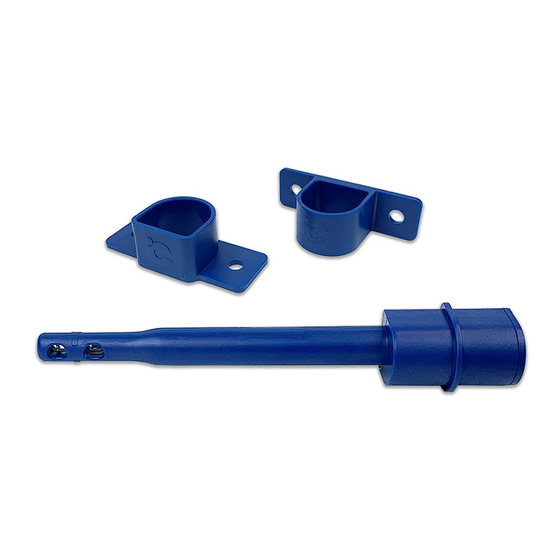
Page 12: Mounting Brackets
Figure 11 S100 with Clamp Side Mount 5.1.2 Mounting Brackets The S100 can be configured with either an end mount or side mount bracket. The end mount bracket provides a mounting flange surface that is parallel to sensor airflow, while the side mount bracket provides a mounting flange surface that is perpendicular to sensor airflow. -
Page 13: Wiring Diagrams
S100 Switch MANUAL Wiring Diagrams Wiring diagrams for the mechanical relay output in various installation scenarios are included below. Isolated Grounds Non-Isolated Grounds S100 MANUAL 66900MN000-A02 Page 13 of 15... -
Page 14: Timing
Multiple Non-Isolated Grounds Timing Warm up time for the S100 includes initial startup delay, sensor heat up time, and alarm delay time. Figure 14 Warm Up Time Warm up time could be longer, or the sensor may not start up, if the sensor is used outside of manufacturer’s specifications. -
Page 15: Degree Controls Inc. Product Warranty
S100 Switch MANUAL 6 Degree Controls Inc. Product Warranty For a period of one (1) year following the date of delivery, and subject to the other provisions of this Warranty Section, DegreeC warrants that all new products that are both (a) manufactured by DegreeC and (b) purchased directly from DegreeC (or an authorized distributor of DegreeC) shall be free of material defects in materials and workmanship.
Need help?
Do you have a question about the S100 and is the answer not in the manual?
Questions and answers