Table of Contents
Advertisement
Quick Links
Advertisement
Table of Contents

Related Manuals for Shift Line Everest II

Summary of Contents for Shift Line Everest II
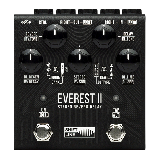
- Page 1 Everest II | Stereo Reverb-Delay User Guide...
-
Page 2: Table Of Contents
Table Of Contents Connections............................3 Connection Options..........................3 MONO Mode..............................3 MONO TO STEREO Mode..........................3 STEREO / DUAL MONO Mode........................... 4 DOUBLE PROCESSING Mode..........................4 Controls..............................4 Primary Parameters (Direct Access)......................... 4 Secondary Parameters (ON / HOLD)......................... 5 Secondary Parameters (TAP / ALT)........................5 Stereo Setup............................5 Setting the Delay Time.......................... -
Page 3: Connections
● two mono signal sources to the LEFT IN and RIGHT IN inputs. The Everest II does not support TRS connections. LEFT OUT is the left channel output. Connect it to the signal receiver. In a mono signal chain, use this output ●... -
Page 4: Stereo / Dual Mono Mode
However, with a bit of practice you can achieve very peculiar results in this mode. Experiment away! Controls The Everest II has multi-function controls: each knob and switch can have several purposes. Primary functions are printed in bold. Secondary functions accessed by holding down the TAP / ALT footswitch are printed on the pedal with a border (and printed here in italics). -
Page 5: Secondary Parameters (On / Hold)
Secondary Parameters (ON / HOLD) ● HOLD + MODE selects among the B, R and M banks. Please see the Banks & Patches section for details. ● HOLD + BEAT selects bypass mode. Set the BEAT switch to the up position for no tails in bypass, to the center position for tails in bypass, or to the down position for Kill Dry with tails in bypass. -
Page 6: Setting The Delay Time
The dry signal path is fully analog throughout the whole pedal. No latency or distortion is applied to the dry signal. Due to the Everest II’s active bypass, there is no audible clicking, and three independent global modes are available (selectable by the BEAT switch while holding down the ON/HOLD footswitch): ●... -
Page 7: Tap/Alt Led
Banks & Patches The 12 patches of the Everest II are organized into 4 banks, each holding 3 patches. Use the MODE switch to select a patch from the bank. To select the B, R or M bank, press and hold the ON/HOLD footswitch, then set the BANK switch to the desired position: ●... -
Page 8: Magenta Bank
Magenta Bank The ON/HOLD LED glows magenta. Set the MODE switch to the desired position: ● Up: Iceman Bright delay and reverb with 80s-style modulation. Delay modulation is based on flanging (the characteristic artifact caused by the tape drives of two tape machines being slightly out of sync) and a classic resonant filter. The reverb practically omits the low frequencies, so there’s no excessive rumbling. -
Page 9: External Parameter Control
○ The TAP/ALT footswitch has no effect on delay time and can only be used to access secondary functions. To connect a MIDI source to the Everest II, use a 6.3mm TRS (stereo) Type A cable.The MIDI channel is set in the config file. -
Page 10: Introduction
The #GLOBAL_INPUT_GAIN parameter controls the volume of the input signal. The standard value (1.0) can be increased or decreased. Decreasing the input gain is needed when using the Everest II in the FX loop of an amp or plugging hot signals into the pedal (for line-level signals, the recommended value of this parameter is 0.25). -
Page 11: Beat Switch Settings
BEAT Switch Settings TAP TEMPO subdivisions for the BEAT switch. You can use any values in the 0.001–1.0 range; however, we recommend using rhythmically connected ones: The UP position of the BEAT switch is set to dotted 8ths by default (0.75). #GLOBAL_TAP_UP 0.75 The CENTER position of the BEAT switch is set to quarter notes by default (1.0). -
Page 12: Ctrl Input Settings For External Parameter Control
Keep in mind that the Everest II is designed for quarter-note clocking with 0.005-1s intervals between two consecutive signals. The lowest clock rate is 60 BPM. The stable clock rate range is 60-300 BPM. Clock precision depends on the stability of control signals. -
Page 13: Patch Settings
Patch Settings Patch Example The config file contains 12 programs (patches) which can all be edited by the user. This is what a complete program block looks like: #PATCH ; Delay Setup #DL.OUT_GAIN #DL.LOOP_kFBK -1.008999944 ; Delay octave up: #DL.OCT_VOL #DL.OCT_kLPF ;... -
Page 14: Patch Position In Banks
(2.0) to let the repeats be set louder than the dry signal. NB! The Everest II was designed as a send effect, so it has no crossmix between the dry and wet signals. The reason is simple: it results in a cleaner sound, and that is how spatial sound processing devices are used in studios (the crossmix option is not worse though). -
Page 15: Reverb Settings
in a 50/50 proportion. The scale of 0.0 to 1.0 is linear. The digits following the decimal point represent crossmix percentages. The three filter types (#DL.LOOP_RESO_MIX_LPF, #DL.LOOP_RESO_MIX_HPF, #DL.LOOP_RESO_MIX_BPF) are parallel branches within the same block. All three can be used together and then mixed to the original signal via the #DL.LOOP_RESO_BLEND parameter. -
Page 16: Saving Parameters And Settings
fly, remember to rescan the config file by changing the MODE switch position. The settings saved in the config file will remain in the Everest II until the file is deleted. If needed, make a backup for the file on a different drive. -
Page 17: Factory Reset
We recommend setting the CC message interval to 17-20ms. The Everest II is connected to the MIDI source via a MIDI Type A 6.3mm TRS jack. The wiring scheme is as follows: MIDI 4 (Source) > TRS RING, MIDI 2 (Shield) >... -
Page 18: Updating The Firmware
NB! An incomplete firmware update can make the pedal unusable. If something goes wrong during the update, the pedal will most likely need to be serviced by Shift Line’s qualified specialists. Please use the contact form if you experience any issues with the firmware update. -
Page 19: Specifications
Specifications ● LEFT IN / RIGHT IN: 6.3 mm, mono, unbalanced, 1 MOhm input impedance. LEFT IN is the main mono input. ● LEFT OUT / RIGHT OUT: 6.3mm, mono, unbalanced, 100 Ohm output impedance. LEFT OUT is the main mono output.
Need help?
Do you have a question about the Everest II and is the answer not in the manual?
Questions and answers