Table of Contents
Advertisement
Quick Links
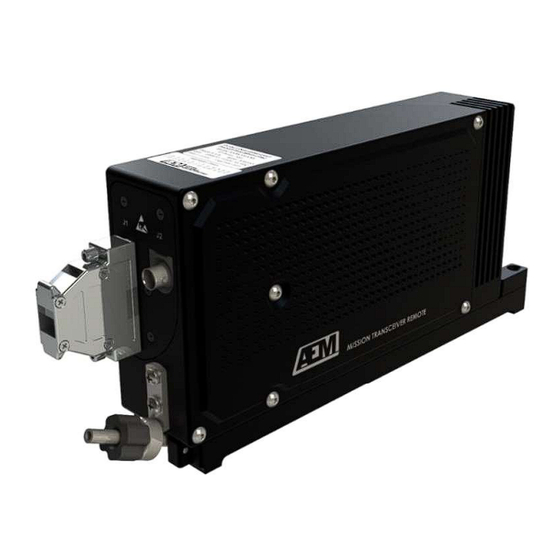
ASM-MTR138-000GNW
Mission Transceiver Remote
INSTALLATION AND OPERATION MANUAL
REV 1.00 May 10, 2024
Anodyne Electronics Manufacturing Corp.
966 Crowley Ave Unit #100
Kelowna, BC, Canada.
V1Y 0L1
Telephone: +1-250-763-1088
Toll Free: +1-888-763-1088
Website: www.aem-corp.com
© 2024 Anodyne Electronics Manufacturing Corp. (AEM),
All Rights Reserved
CONFIDENTIAL AND PROPRIETARY TO ANODYNE ELECTRONICS MANUFACTURING CORP.
Advertisement
Table of Contents

Summary of Contents for AEM ASM-MTR138-000GNW
- Page 1 REV 1.00 May 10, 2024 Anodyne Electronics Manufacturing Corp. 966 Crowley Ave Unit #100 Kelowna, BC, Canada. V1Y 0L1 Telephone: +1-250-763-1088 Toll Free: +1-888-763-1088 Website: www.aem-corp.com © 2024 Anodyne Electronics Manufacturing Corp. (AEM), All Rights Reserved CONFIDENTIAL AND PROPRIETARY TO ANODYNE ELECTRONICS MANUFACTURING CORP.
- Page 2 © 2024 Anodyne Electronics Manufacturing Corp. (AEM), All Rights Reserved This publication is the property of AEM and is protected by Canadian copyright laws. No part of this document may be reproduced or transmitted in any form or by any means including electronic, mechanical, photocopying, recording, or otherwise, without the prior written permission of AEM.
- Page 3 MTR138-000GNW Mission Transceiver Remote Installation and Operation Manual Prepared By: Checked By: Approved By: AEM MANUAL REVISIONS Section Revision Number Revision Description Date Rev: 1.00 Initial release 10-May-2024 Rev. 1.00 May 10, 2024 Page ii ENG-FORM 800-0101.DOTX CONFIDENTIAL AND PROPRIETARY TO ANODYNE ELECTRONICS MANUFACTURING CORP.
-
Page 4: Table Of Contents
MTR138-000GNW Mission Transceiver Remote Installation and Operation Manual Table of Contents SECTION 1.0 DESCRIPTION....................1 1.1 Introduction......................... 1 1.2 Product Description ....................1 1.3 Design Features ......................2 1.3.1 Transmit Features................... 2 1.3.2 Receive Features.................... 2 1.3.3 Guard Receiver ....................2 1.3.4 Subaudible Signalling Tones ................ - Page 5 MTR138-000GNW Mission Transceiver Remote Installation and Operation Manual 3.5.2 Transmit Interruption..................16 3.5.3 Transmit Timeout...................16 3.6 Receive Operational Features ...................16 3.6.1 Receiver Volume ...................16 3.6.2 Scan Channels ....................16 3.6.3 Scanning Modes ....................17 3.6.4 Squelch modes....................18 3.6.5 Discrete RF Signal Indicator ................19 3.6.6 Sidetone ......................19 3.6.7 Communication Lockout ................19 Rev.
-
Page 6: Section 1.0 Description
MTR138-000GNW Mission Transceiver Remote Installation and Operation Manual Section 1.0 Introduction Information in this section includes product description, design features and specifications for the MTR138-000GNW Mission Transceiver Remote, herein subsequently referred to as MTR138. Review all notes, warnings, and cautions. Product Description The MTR138 is a wideband and narrowband capable remote mount transceiver containing a synthesized Guard Receiver. -
Page 7: Design Features
MTR138-000GNW Mission Transceiver Remote Installation and Operation Manual Design Features The MTR138 is a remote mount FM transceiver that supports 128 channels. Each channel s bandwidth can be individually set as wideband or narrowband. A channel s transmit and receive frequency can be set with a frequency increment of 2.5 kHz. The MTR138 has no local user controls and is interfaced and controlled from an appropriately configured and attached device that adheres to the command-and-control protocol detailed in the Interface Control Data (ICD) document. -
Page 8: Subaudible Signalling Tones
MTR138-000GNW Mission Transceiver Remote Installation and Operation Manual 1.3.4 Subaudible Signalling Tones The MTR138 supports two types of in band signalling; Continuous Tone-Coded Squelch System (CTCSS) and Continuous Digital-Coded Squelch System (CDCSS). CTCSS encoding supports 50 different tone codes and CDCSS supports 106 different tone codes. -
Page 9: Section 2.0 Installation
- Certificate of Conformity or Release Certification Verify that all items are present before proceeding and report any shortage immediately to your supplier. Warranty Please refer to the standard product warranty conditions available on our website, www.aem-corp.com Installation Procedure 2.4.1 Warnings WARNING:... -
Page 10: Cautions
MTR138-000GNW Mission Transceiver Remote Installation and Operation Manual 2.4.2 Cautions CAUTION: Do not bundle any lines from this unit with transmitter coax lines. Do not bundle any logic, audio, or DC power lines from this unit with 400Hz wiring or AC power lines. Do not position this unit next to any device with a strong alternating magnetic field such as an inverter or significant interference to operation may occur. -
Page 11: Mechanical Installation
MTR138-000GNW Mission Transceiver Remote Installation and Operation Manual Verify that the selected circuit breaker size and wire gauge are adequate for the installation using the techniques specified in AC43.13-1B Change 1, Paragraphs 11-47 through 11-51 and 11-66 through 11-69. Mechanical Installation 2.5.1 MTR-VT1 Mounting Tray to Airframe Installation Procedure Attach the MTR-VT1 mounting tray to the airframe using the counter sunk mounting... -
Page 12: Antennas
MTR138-000GNW Mission Transceiver Remote Installation and Operation Manual 2.5.3 Antennas Proper antenna installation is vital to ensure reliable operation of the MTR138 and the aircraft. For best results the following should be taken into consideration where applicable: a) The aircraft manufacturers installation instructions are followed. b) The antennas are as widely separated as practically possible and clear of large aircraft obstructions. -
Page 13: Bonding
MTR138-000GNW Mission Transceiver Remote Installation and Operation Manual 2.6.2 Bonding If required, bonding is normally achievable through the mounting points during installation of the product using conductive hardware. If the hardware and/or mounting location/surface is non-conductive, then the use of a bonding strap to an airframe ground point is required. -
Page 14: Adjustments And Connections
An installation kit P/N MTR138-IKC (crimp), vertical mounting tray P/N MTR-VT1 and mounting hardware are required to complete the installation. The MTR138-IKC install kit consists of the following: Description Manufacturer Mfr Part # AEM Part # D-Sub, Socket, 25 Crimp Housing Amphenol L177RR-B25S 20-21-025 Contact, Socket, Crimp, 20-24... -
Page 15: Installation Drawings
MTR-VT1-922-0 1.00 Mechanical Installation 107208+ Section 2.0 Ends Following Above Documents Document must be requested directly from AEM and is not included in this document. Rev. 1.00 May 10, 2024 Page 10 of 19 ENG-FORM 800-0101.DOTX CONFIDENTIAL AND PROPRIETARY TO ANODYNE ELECTRONICS MANUFACTURING CORP. - Page 18 UNLESS OTHERWISE SPECIFIED: NAME DATE KELOWNA BC CANADA DIMENSIONS ARE IN INCHES [MM] (250)-763-1088 21-Apr-2022 DRAWN TOLERANCES: WWW.AEM-CORP.COM FRACTIONAL_____________ ±0.0625" CHECKED ANGULAR_______________ ±0.5° TITLE: MISSION TRANSCEIVER REMOTE, TWO DECIMAL PLACE____ ±0.010" APPROVED THREE DECIMAL PLACE___ ±0.005" W/GUARD CONNECTOR MAP MATERIAL:...
- Page 19 DECLARATION OF DESIGN AND PERFORMANCE Part No.: MTR138-000GNW Description: Mission Transceiver Remote w/Guard Document: MTR138-000GNW-618-0 Rev.: 1.00 Prepared By: Checked By: Approved By: Subject of Declaration of Design and Performance MTR138-000GNW Mission Transceiver Remote with Synthesized Guard Receiver Product Description The MTR138-000GNW is a Wideband and Narrowband capable remote mount transceiver containing a synthesized guard receiver System (MTACS) family.
- Page 20 MTR138-000GNW Declaration of Design and Performance 3. Applicable Documents Document No. Equipment Design Specification MTR138-000GNW-000-0 Mechanical Installation MTR138-000GNW-922-0 Equipment Interconnect Drawing MTR138-000GNW-403-0 Equipment Build Standard MTR138-000GNW-721-0 Installation and Operation Manual MTR138-IOMTR138-000GNW Qualification Program MTR138-000GNW-610-0 External Test Lab Procedures and MTR138-000GNW-610-2 DO-160G Sec.
- Page 21 MTR138-000GNW Declaration of Design and Performance Mechanical / Electrical Specification or Data Characteristics Mounting Orientation: All mounting orientations are allowed. Mounting Method: Mounting Tray MTR-VT1. Custom ¼ ATR style tray. Dimensions: Width: 2.30 in (58.4 mm) MAX Height: 4.80 in (121.9 mm) MAX Length (Body): 9.70 in (246.4 mm) MAX Weight:...
- Page 22 MTR138-000GNW Declaration of Design and Performance Section 4 Continued from Previous Page Mechanical / Electrical Specification or Data Characteristics Output Signals: RT Installed Quantity: Circuitry Type: Single Ended Active Low (Ground) Rated Level: 1.0 Vdc MAX Current In: 15 mA MAX Main SQ Disable Out Quantity: Circuitry Type:...
- Page 23 MTR138-000GNW Declaration of Design and Performance Performance Parameters Specification or Standard Reference (Standard Definitions) Standard Intermittent Duty TIA-603-E, Sec. 1.3.2.2 MTR138-000GNW-613-0 Cycle MTR138-000GNW-652-0 Duty Cycle (HI Power): 4 min. RX / 1 min. TX for 8 hrs (20%) See Sec. 11, Note 15 15 min.
- Page 24 MTR138-000GNW Declaration of Design and Performance Performance Parameters Specification or Standard Reference (Standards for Receivers) Conducted Spurious Output TIA-603-E, Sec. 3.1.2 MTR138-000GNW-613-0 Emission Level: MTR138-000GNW-652-0 Reference Sensitivity TIA-603-E, Sec. 3.1.4 MTR138-000GNW-613-0 Sensitivity: -114.5 dBm (0.42 µV) at 12 dB SINAD See Sec.
- Page 25 MTR138-000GNW Declaration of Design and Performance Section 6 Continued from Previous Page Performance Parameters Specification or Standard Reference (Standards for Receivers) Hum and Noise Ratio TIA-603-E, Sec. 3.1.11 MTR138-000GNW-613-0 MTR138-000GNW-652-0 Unsquelched Wideband: 45 dB See Sec. 11, Note 1 Narrowband: 34 dB Squelched: -57 dBW...
- Page 26 MTR138-000GNW Declaration of Design and Performance Section 6 Continued from Previous Page Performance Parameters Specification or Standard Reference (Standards for Receivers) Blocking Rejection (Class A) TIA-603-E, Sec. 3.1.21 MTR138-000GNW-613-0 MTR138-000GNW-652-0 Receiver Blocking See Sec. 11, Note 1 Rejection: Receiver Opening Time after TIA-603-E, Sec.
- Page 27 MTR138-000GNW Declaration of Design and Performance Performance Parameters Specification or Standard Reference (Standards for Transmitters) Conducted Carrier Output TIA-603-E, Sec. 3.2.1 MTR138-000GNW-613-0 Power Rating MTR138-000GNW-652-0 See Sec. 11, Note 11 FM, Power Output, HI: 40 dBm ± 1 dB (7.94 -12.59 W) FM, Power Output, LO: 30 dBm ±...
- Page 28 MTR138-000GNW Declaration of Design and Performance Section 7 Continued from Previous Page Performance Parameters Specification or Standard Reference (Standards for Transmitters) FM Hum and Noise Ratio TIA-603-E, Sec. 3.2.8 MTR138-000GNW-613-0 (Tested in HI Power Only) Wideband: Narrowband: AM Hum and Noise Ratio TIA-603-E, Sec.
- Page 29 MTR138-000GNW Declaration of Design and Performance Performance Parameters Specification or Standard Reference (Standards for Subaudible Signaling) Squelch Opening SINAD TIA-603-E, Sec. 3.4.1 MTR138-000GNW-613-0 SINAD, CTCSS: 12 dB MTR138-000GNW-652-0 SINAD, CDCSS: 12 dB See Sec. 11, Note 9 Receive Audio Attack Time TIA-603-E, Sec.
- Page 30 MTR138-000GNW Declaration of Design and Performance Section 8 Continued from Previous Page Performance Parameters Specification or Standard Reference (Standards for Subaudible Signaling) Receiver Audio Response TIA-603-E, Sec. 3.4.8 MTR138-000GNW-613-0 MTR138-000GNW-652-0 See Sec. 11, Notes 2, 14 350-3000 Hz (Standard): -6 dB/Octave with +1/-3 dB/Octave variance, De-emphasis 350-500 Hz: Standard with an additional...
- Page 31 MTR138-000GNW Declaration of Design and Performance Section 8 Continued from Previous Page Performance Parameters Specification or Standard Reference (Standards for Subaudible Signaling) Transmitter Subaudible TIA-603-E, Sec. 3.4.17 MTR138-000GNW-613-0 Deviation MTR138-000GNW-652-0 Deviation Limits: CTCSS Wideband: 500 - 1000 Hz (For Rated Deviation of ± 5.0 kHz) CTCSS Narrowband: 350 - 600 Hz (For Rated Deviation of ±...
- Page 32 MTR138-000GNW Declaration of Design and Performance Performance Parameters Specification or Standard Reference (AEM Requirements) Current Requirements MTR138-000GNW-610-0 Sec. 8.1 MTR138-000GNW-613-0 See Sec. 11, Note 18 TX HI Power: < 2.50 A TX LO Power: < 1.00 A RX Unsquelched: < 300 mA RX Squelched: <...
- Page 33 MTR138-000GNW Declaration of Design and Performance Environmental Parameter Specification or Standard References Temperature RTCA/DO-160G, Sec. 4.5, Cat. B2 MTR138-000GNW-613-0 Section 4.3.1 Ground Survival Low Temp: -55 °C Performance Parameters: 6b, 6c, 6d, 6h, 6i, 6j, 6k, Short-Time Operating Low Temp: -45 °C 7a, 7b, 7c, 7g, 7h, 9c, Operating Low Temp:...
- Page 34 MTR138-000GNW Declaration of Design and Performance Section 10 Continued from Previous Page Environmental Parameter Specification or Standard References Explosive Atmosphere RTCA/DO-160G, Sec. 9, Cat. H MTR138-000GNW-613-0 Section 4.3.4 Maximum Temperature at Performance Parameters: Suspected Components and Not Applicable Surfaces 204 °C Waterproofness RTCA/DO-160G, Sec.
-
Page 35: Section 3.0 Operation
MTR138-000GNW Declaration of Design and Performance Section 10 Continued from Previous Page Environmental Parameter Specification or Standard References Power Input RTCA/DO-160G, Sec.16, Cat. ZXX MTR138-000GNW-613-0 Section 4.3.6 Normal Operating Conditions (DC): Performance Parameters Maximum Operating Voltage: +32.2 Vdc (Norm. Op. Conditions) 6b, 6h, 6i, 7a, 7g, 7h, Nominal Operating Voltage: +28.0 Vdc... - Page 36 MTR138-000GNW Declaration of Design and Performance Section 10 Continued from Previous Page Environmental Parameter Specification or Standard References Induced Signal Susceptibility RTCA/DO-160G, Sec. 19, Cat. ZCE MTR138-000GNW-613-0 Section 4.3.8 Magnetic Fields into Equipment: 20 Arms @ 400 Hz Performance Parameters: Electric Fields into Equipment: 170 Vrms @ 400 Hz 6b, 6i, 7a, 7g...
- Page 37 MTR138-000GNW Declaration of Design and Performance Section 10 Continued from Previous Page Environmental Parameter Specification or Standard References Radio Frequency Susceptibility, Continued During testing, the unit under test experienced degraded SINAD performance below 12 dB at the frequencies noted below. In all cases the unit under test fully recovered after exposure. Required Reduced Threat Level to Modulation...
- Page 38 MTR138-000GNW Declaration of Design and Performance Section 10 Continued from Previous Page Environmental Parameter Specification or Standard References Lightning Induced Transient RTCA/DO-160G, Sec. 22, MTR138-000GNW-652-0 Susceptibility Cat. XXJ3L3 Performance Parameters: Pin Injection Tests: Not Tested MTR138-100-610-4 Cable Bundle Tests: Single / Multiple Stroke: Waveforms 1 &...
- Page 39 Instantaneous Peak and Steady State Deviations shall not exceed Rated System Deviation at any audio frequency or change in level. AEM has chosen to use 3 dB below rated output as the point of record, rather than 90% of rated output as stated in TIA-603-E.
- Page 40 Signature: Anodyne Electronics Manufacturing Corp. Kelowna, BC Trevor Lynch-Staunton, P.Eng. Canada Chief Technical Officer aem-corp.com Anodyne Electronics Manufacturing Corp. End of Declaration of Design and Performance Page 22 of 22 May 01, 2024 Rev. 1.00 ENG-FORM: 618-0101.DOTX CONFIDENTIAL AND PROPRIETARY TO ANODYNE ELECTRONICS MANUFACTURING CORP.
- Page 41 INSTALLATION APPROVAL TEST PROCEDURE Part #: MTR138-000GNW Description: Mission Transceiver Remote w/Guard Document : MTR138-000GNW-634-0 Rev: 1.00 Purpose The installation approval test procedure is intended to identify any interference the MTR138-000GNW transceiver may cause with existing aircraft systems. Methodology Test Setup Many of the post installation Electromagnetic Interference (EMI) tests can be completed on the ground.
- Page 42 MTR138-000GNW Installation Approval Test Procedure Test Methodology Perform a general function test of the MTR138 and identify the antenna VSWR. Monitor the GPS for degradation in satellite status, availability, or flags. Monitor the VHF communication for any noise, audio signals or anomalies. Monitor the VOR/ILS navigation systems for any irregular movement of needles or flags.
- Page 43 MTR138-000GNW Installation Approval Test Procedure Functional Test Initial Installation Functional Test The MTR138 transceiver should be installed and function tested before beginning operations. It is also recommended to perform a forward/reverse power test using an in-line wattmeter to check the antenna Voltage Standing Wave Ratio (VSWR). No more than 10% of power should be reflected.
- Page 44 MTR138-000GNW Installation Approval Test Procedure VHF Communications Functional Test Identify if the operational range of the MTR138 overlaps with any of the image frequencies of the VHF communications. If any overlap exists, select a set of image frequencies (IF) that will place MTR138 as close to the image frequencies as possible. It is recommended to only use one of the possible frequency sets.
- Page 45 MTR138-000GNW Installation Approval Test Procedure VOR/ILS Navigation Systems Functional Test Identify if the operational range of the MTR138 overlaps with any of the image frequencies of the VOR/ILS navigation systems. If any overlap exists, select two sets of image frequencies (IF) that will place MTR138 as close to the IF as possible. Ensure that one frequency set lies within the localizer frequency range and the other lies within the VOR frequency range.
- Page 46 MTR138-000GNW Installation Approval Test Procedure Glide Slope Functional Test Note: To avoid interference generated by nearby structures and aircraft it is recommended to perform the following tests outside and as far away from all structures and aircraft as is practical. Utilize a portable glide slope generator to provide sufficient signal strength to clearly activate the indicator needle and hide all flags.
- Page 47 MTR138-000GNW Installation Approval Test Procedure If the ground test failed and interference exists, flight testing must be conducted. Utilize the tables below and determine the glide slope frequency which is based on the localizer frequency of the Instrument Landing System (ILS) that will be used. Set the MTR138 to half of the identified glide slope frequency.
- Page 48 MTR138-000GNW Installation Approval Test Procedure FREQUENCIES RESULTS G/S #1 MTR138 PASS FAIL 334.7 (108.1) 167.3500 FREQUENCIES RESULTS G/S #2 MTR138 PASS FAIL 334.7 (108.1) 167.3500 Notes: Rev. 1.00 Jan 12, 2023 Page 8 of 10 ENG-FORM: 634-0100.DOTX CONFIDENTIAL AND PROPRIETARY TO ANODYNE ELECTRONICS MANUFACTURING CORP.
- Page 49 MTR138-000GNW Installation Approval Test Procedure Autopilot or Stability Augmentation System Functional Test 4.6.1 Identify frequencies that are at the top, middle, and bottom of the MTR138 frequency range and use them throughout Section 4.6. Top of frequency range: Middle of frequency range: Bottom of frequency range: 4.6.2 Activate the autopilot or stability augmentation system at a safe altitude and transmit...
- Page 50 MTR138-000GNW Installation Approval Test Procedure Electrical Instruments and Anomalies 4.7.1 List the power plant, fuel and other electric instruments in the chart provided and note any anomalies that occur operating the MTR138. Assess the results. STEP SYSTEM PASS FAIL NOTES Com 1 Com 2 GPS 1...
- Page 52 MTR VERTICAL TRAY MOUNT MECHANICAL INSTALLATION L9015 MTR-VT1 1.00...
-
Page 53: Introduction
RS-422 interface. The supported command and control protocol is specified in the MTR138-000GNW-007 Interface Control Data (ICD) document (available upon direct request to AEM). In addition to the ICD, the operations manual of the appropriately configured controlling device should be consulted for all operational information. -
Page 54: Channel Selection
MTR138-000GNW Mission Transceiver Remote Installation and Operation Manual All remaining run time configurable settings are not required to be sent as part of the start-up sequence, as the MTR138 is configured with default settings. It is recommended to send at minimum the following commands to ensure the desired operational settings are applied at start-up. - Page 55 MTR138-000GNW Mission Transceiver Remote Installation and Operation Manual 3.4.3.1 CTCSS Sub-Audible Tones The MTR138 can utilize the 50 CTCSS tone codes (38 standard and 12 extended tones) as defined below: CTCSS Tones FREQ FREQ FREQ FREQ 97.4 136.5 192.8 71.9 141.3 203.5 74.4...
-
Page 56: Simplex/Duplex
MTR138-000GNW Mission Transceiver Remote Installation and Operation Manual 3.4.4 Simplex/Duplex The MTR138 can operate in the Simplex or Semi-Duplex communication mode. This selection is global to all channels and is selected using the Simplex/Duplex command. Simplex: The MTR138 transmits and receives on the set channel s receive frequency and utilizes the channel s receive sub-audible tones. -
Page 57: Error Recovery
MTR138-000GNW Mission Transceiver Remote Installation and Operation Manual 3.4.7.2 Serial Number Query The Serial Number query can be used to identify the factory programmed serial number of the MTR138. 3.4.7.3 Model Number Query The Model Number query can be used to identify the Model number of the MTR138. 3.4.7.4 Firmware Version Query The Firmware Version query can be used to identify the Firmware Version of the MTR138. -
Page 58: Transmit Operational Features
MTR138-000GNW Mission Transceiver Remote Installation and Operation Manual Transmit Operational Features 3.5.1 Transmit Power The MTR138 can be set to use one of two transmit power levels that will be applied to all channels: High Power (10W): This mode is advisable for transmitting over long distances or in high noise environments. -
Page 59: Scanning Modes
MTR138-000GNW Mission Transceiver Remote Installation and Operation Manual Home Channel: When entering the scanning mode, the current operating channel is automatically assigned as the Home channel by the MTR138. The Home channel is always included in the scanning list for every scanning mode. -
Page 60: Squelch Modes
MTR138-000GNW Mission Transceiver Remote Installation and Operation Manual 3.6.3.2 Priority Scanning: Listed below are the operational functions that occur while in the Priority Scanning mode: a) The MTR138 continuously scans the priority channels (P1, P2) and the Home channel in the listed priority order until the scan mode is exited. b) Once an RF signal is detected, the MTR138 remains parked receiving on that channel. -
Page 61: Discrete Rf Signal Indicator
MTR138-000GNW Mission Transceiver Remote Installation and Operation Manual 3.6.4.1 Automatic Squelch The MTR138 mutes all noise and will only allow the received audio on the current Main and Guard channels to pass to the headset phones output if the following conditions are met: a) The unsquelch signal threshold, as listed in the applicable DDP, is breached.
Need help?
Do you have a question about the ASM-MTR138-000GNW and is the answer not in the manual?
Questions and answers