ASROCK M3A760GMH Manual
Hide thumbs
Also See for M3A760GMH:
- Installation manual (17 pages) ,
- Specifications (1 page) ,
- User manual (59 pages)
Table of Contents
Advertisement
Copyright Notice:
Copyright Notice:
Copyright Notice:
Copyright Notice:
Copyright Notice:
No part of this installation guide may be reproduced, transcribed, transmitted, or trans-
lated in any language, in any form or by any means, except duplication of documen-
tation by the purchaser for backup purpose, without written consent of ASRock Inc.
Products and corporate names appearing in this guide may or may not be registered
trademarks or copyrights of their respective companies, and are used only for identifica-
tion or explanation and to the owners' benefit, without intent to infringe.
Disclaimer:
Disclaimer:
Disclaimer:
Disclaimer:
Disclaimer:
Specifications and information contained in this guide are furnished for informational
use only and subject to change without notice, and should not be constructed as a
commitment by ASRock. ASRock assumes no responsibility for any errors or omissions
that may appear in this guide.
With respect to the contents of this guide, ASRock does not provide warranty of any kind,
either expressed or implied, including but not limited to the implied warranties or
conditions of merchantability or fitness for a particular purpose. In no event shall
ASRock, its directors, officers, employees, or agents be liable for any indirect, special,
incidental, or consequential damages (including damages for loss of profits, loss of
business, loss of data, interruption of business and the like), even if ASRock has been
advised of the possibility of such damages arising from any defect or error in the guide
or product.
This device complies with Part 15 of the FCC Rules. Operation is subject to the
following two conditions:
(1) this device may not cause harmful interference, and
(2) this device must accept any interference received, including interference that
may cause undesired operation.
CALIFORNIA, USA ONLY
The Lithium battery adopted on this motherboard contains Perchlorate, a toxic
substance controlled in Perchlorate Best Management Practices (BMP) regulations
passed by the California Legislature. When you discard the Lithium battery in
California, USA, please follow the related regulations in advance.
"Perchlorate Material-special handling may apply, see
www.dtsc.ca.gov/hazardouswaste/perchlorate"
ASRock Website: http://www.asrock.com
Copyright©2010 ASRock INC. All rights reserved.
ASRock
Published October 2010
M3A760GMH
Motherboard
1 1 1 1 1
Advertisement
Table of Contents

Related Manuals for ASROCK M3A760GMH


Summary of Contents for ASROCK M3A760GMH
- Page 1 ASRock. ASRock assumes no responsibility for any errors or omissions that may appear in this guide. With respect to the contents of this guide, ASRock does not provide warranty of any kind, either expressed or implied, including but not limited to the implied warranties or conditions of merchantability or fitness for a particular purpose.
-
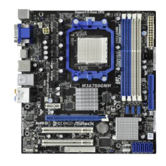
Page 2: Motherboard Layout
USB 2.0 Header (USB6_7, Blue) (HD_AUDIO1, White) Chassis Fan Connector (CHA_FAN1) PCI Slots (PCI1-2) USB 2.0 Header (USB8_9, Blue) PCI Express 2.0 x16 Slot (PCIE2; Blue) Southbridge Controller PCI Express 2.0 x1 Slot (PCIE1; White) SPI Flash Memory (8Mb) Power Fan Connector (PWR_FAN1) -
Page 3: Speed Led
Optical SPDIF Out Port VGA/DVI-D Port Line In (Light Blue) PS/2 Keyboard Port (Purple) * There are two LED next to the LAN port. Please refer to the table below for the LAN port LED indications. LAN Port LED Indications ACT/LINK... -
Page 4: Package Contents
ASRock’s commitment to quality and endurance. In this manual, chapter 1 and 2 contain introduction of the motherboard and step-by-step guide to the hardware installation. Chapter 3 and 4 contain the configuration guide to BIOS setup and information of the Support CD. -
Page 5: Specifications
- Micro ATX Form Factor: 9.6-in x 9.0-in, 24.4 cm x 22.9 cm - Support for Socket AM3 processors: AMD Phenom II X6 / X4 / X3 / X2 (except 920 / 940) / Athlon II X4 / X3 / X2 / Sempron processors - Six-Core CPU Ready... - Page 6 - 1 x Optical SPDIF Out Port - 6 x Ready-to-Use USB 2.0 Ports - 1 x eSATAII Connector - 1 x RJ-45 LAN Port with LED (ACT/LINK LED and SPEED LED) - HD Audio Jack: Rear Speaker/Central/Bass/Line in/ Front Speaker/Microphone (see CAUTION 6) Connector - 5 x Serial ATAII 3.0Gb/s connectors, support RAID (RAID 0,...
- Page 7 Overclocking may affect your system stability, or even cause damage to the components and devices of your system. It should be done at your own risk and expense. We are not responsible for possible damage caused by overclocking.
- Page 8 Before installing SATAII hard disk to SATAII connector, please read the “SATAII Hard Disk Setup Guide” on page 26 of “User Manual” in the support CD to adjust your SATAII hard disk drive to SATAII mode. You can also connect SATA hard disk to SATAII connector directly.
- Page 9 USB flash drive or hard drive must use FAT32/16/12 file system. 11. The software name itself – OC DNA literally tells you what it is capable of. OC DNA, an exclusive utility developed by ASRock, provides a conve- nient way for the user to record the OC settings and share with others.
-
Page 10: Pre-Installation Precautions
Installation Installation Installation This is a Micro ATX form factor (9.6-in x 9.0-in, 24.4 cm x 22.9 cm) motherboard. Before you install the motherboard, study the configuration of your chassis to en- sure that the motherboard fits into it. Pre-installation Precautions... -
Page 11: Installation Of Cpu Fan And Heatsink
Step 4. When the CPU is in place, press it firmly on the socket while you push down the socket lever to secure the CPU. The lever clicks on the side tab to indicate that it is locked. -
Page 12: Installation Of Memory Modules (Dimm)
(the same brand, speed, size and chip- type) DDR3 DIMM pair in the slots of the same color. In other words, you have to install identical DDR3 DIMM pair in Dual Channel A (DDR3_A1 and DDR3_B1;... -
Page 13: Installing A Dimm
Unlock a DIMM slot by pressing the retaining clips outward. Step 2. Align a DIMM on the slot such that the notch on the DIMM matches the break on the slot. The DIMM only fits in one correct orientation. It will cause permanent damage to the motherboard and the DIMM if you force the DIMM into the slot at incorrect orientation. -
Page 14: Expansion Slots (Pci And Pci Express Slots)
2.4 Expansion Slots (PCI and PCI Express Slots) 2.4 Expansion Slots (PCI and PCI Express Slots) There are 2 PCI slots and 2 PCI Express slots on this motherboard. PCI Slots: PCI slots are used to install expansion cards that have the 32-bit PCI interface. PCIE Slots: PCIE1 (PCIE x1 slot;... -
Page 15: Dual Monitor And Surround Display Features
VGA card to this motherboard. This motherboard also provides independent display controllers for DVI-D, D-Sub and HDMI to support dual VGA output so that DVI-D, D-sub and HDMI can drive same or different display contents. - Page 16 [512MB] to enable the function of VGA/D-sub. Please make sure that the value you select is less than the total capability of the system memory. If you do not adjust the BIOS setup, the default value of “Share Memory”, [Auto], will disable VGA/D-Sub function when the add-on VGA card is inserted to this motherboard.
- Page 17 Settings” tab so that you can adjust the parameters of the multi-monitor according to the steps below. A. Click the number ”2” icon. B. Click the items “This is my main monitor” and “Extend the desktop onto this monitor”. C. Click “OK” to save your change.
-
Page 18: Jumpers Setup
CLRCMOS1 for 5 seconds. However, please do not clear the CMOS right after you update the BIOS. If you need to clear the CMOS when you just finish updating the BIOS, you must boot up the system first, and then shut it down before you do the clear-CMOS action. -
Page 19: Onboard Headers And Connectors
Floppy Connector (33-pin FLOPPY1) (see p.2 No. 26) the red-striped side to Pin1 Note: Make sure the red-striped side of the cable is plugged into Pin1 side of the connector. Primary IDE connector (Blue) (39-pin IDE1, see p.2 No. 10) - Page 20 HDA to function correctly. Please follow the instruction in our manual and chassis manual to install your system. 2. If you use AC’97 audio panel, please install it to the front panel audio header as below: A.
- Page 21 Though this motherboard provides 4-Pin CPU fan (Quiet Fan) support, the 3-Pin CPU fan still can work successfully even without the fan speed control function. If you plan to connect the 3-Pin CPU fan to the CPU fan connector on this motherboard, please connect it to Pin 1-3.
- Page 22 Though this motherboard provides 24-pin ATX power connector, it can still work if you adopt a traditional 20-pin ATX power supply. To use the 20-pin ATX power supply, please plug your power supply along with Pin 1 and Pin 13.
-
Page 23: Driver Installation
Driver Installation Guide Driver Installation Guide To install the drivers to your system, please insert the support CD to your optical drive first. Then, the drivers compatible to your system can be auto-detected and listed on the support CD driver page. Please follow the order from up to bottom side to install those required drivers. -
Page 24: Installing Windows Vista
Untied Overclocking function, please enter “Overclock Mode” option of BIOS setup to set the selection from [Auto] to [CPU, PCIE, Async.]. Therefore, CPU FSB is untied during overclocking, but PCI / PCIE buses are in the fixed mode so that FSB can operate under a more stable overclocking environment. -
Page 25: Bios Information
BIOS Setup utility; otherwise, POST continues with its test routines. If you wish to enter BIOS Setup after POST, please restart the system by pressing <Ctl> + <Alt> + <Delete>, or pressing the reset button on the system chassis. The BIOS Setup program is designed to be user-friendly. - Page 26 ASRock. ASRock Micro ATX: 9,6 x 9,0 / 24,4 x 22,9 ASRock ASRock Serial ATA (SATA) ( ASRock M3A760GMH Motherboard...
- Page 27 9,6 x 9,0 / 2 4 , 4 x 2 2 , 9 ASRock M3A760GMH Motherboard...
- Page 28 Hot-Plug ASRock M3A760GMH Motherboard...
- Page 29 ASRock M3A760GMH Motherboard...
- Page 30 ASRock M3A760GMH Motherboard...
- Page 31 ASRock M3A760GMH Motherboard...
- Page 32 ASRock M3A760GMH Motherboard...
- Page 33 ASRock M3A760GMH Motherboard...
- Page 34 DDR3_A1 DDR3_B1 DDR3_A2 DDR3_B2 (3)* ASRock M3A760GMH Motherboard...
- Page 35 DIMM DIMM DIMM ASRock M3A760GMH Motherboard...
- Page 36 ASRock M3A760GMH Motherboard...
- Page 37 Short Open CMOS CMOS ASRock M3A760GMH Motherboard...
- Page 38 1 SATAII_1 SATAII_2 SATAII_3 SATAII_4 SATAII_5 (PORT 0) (PORT 1) (PORT 2) (PORT 3) (PORT 4) ASRock M3A760GMH Motherboard...
- Page 39 IR1) ASRock M3A760GMH Motherboard...
- Page 40 ASRock M3A760GMH Motherboard...
- Page 41 PANEL1) ATX. ASRock M3A760GMH Motherboard...
- Page 42 12V-ATX ATX 12 , COM- ASRock M3A760GMH Motherboard...
- Page 43 ASRock M3A760GMH Motherboard...
- Page 44 ASRock M3A760GMH Motherboard...
- Page 45 BIOS Setup Power-On-Self-Test – POST POST BIOS Setup POST Ctrl> + <Alt> + <Delete BIOS Setup ASRock M3A760GMH Motherboard...
Need help?
Do you have a question about the M3A760GMH and is the answer not in the manual?
Questions and answers