Advertisement
Quick Links
Quick start 2-Wire v3.2
13
EMM.630(M)CT-MID (
(Rogowski coils)
EMM.630MCT-RC
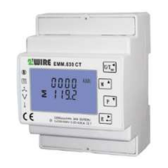
The EMM.630 (M)CT is an advanced 3 phase
energy monitor with direct connection to the
mains for measuring reference voltages and 3
connections for connecting the current coils 1A or
5A CT or in case of the EMM.630MCT-RC directly
coupled Rogowski coils, with which consumers
>100A can be measured. The meter is configured
via the touch buttons on the front panel and the
LCD display. The bi-directional measurement
measures consumption on mono, 3x230V or 3x380V+N power supplies.
Both active and reactive power are measured. The reading of the
consumption values can be done via the display or on the connected web
server. The module is encased in a 4 module wide DIN rail housing. In
addition to an RS485 connection, this energy meter also has 2 pulse
outputs, 1 of which is adjustable.
1. Connect:
Caution
1: To avoid voltage surges: first connect coil conductors to the
meter, only then coil to clip current conductors!! Installation of the
current coil is only carried out by a qualified electrician!! Wear safety
goggles every time you use the coils!!
Caution
2: With the EMM.630 CT-MID, the coil type can only be
entered once, see point 2. Configuration on the display
Caution 3: After connecting the coils, check the polarity via the display
button "P", if the power is negative (Watt) or negative PF, then open
the coil and turn it over, unless there is injection by solar panels!
Attention 4: The measured reference voltage and the measured
current MUST be on the same phase: ALWAYS test with voltmeter :
Voltage between conductor reference voltage and conductor current
coil must be ZERO, otherwise you have a wrong measurement!! Here
you can use the voltage drain terminals type UAD (see website)
EMM.630 (M)CT: Mono-phase connection
On display: Set as mono-phase: SYS 1P2
Reference Voltage: Neuter on Terminal 1; Phase on Terminal 4
Power coil: Keep current arrow on coil, arrow pointing to
consumer! Black conductor (=GND) on Terminal 19; White Conductor on
Terminal 20
Module supply voltage: Neuter on Terminal 6,Phase on Terminal 5
Remark : Loop-Loop Clamp according to meter Clamp 7= Clamp 5;
Terminal 8= Terminal 6
Connecting Modbus: Terminal A (=13) and B (=14) and GROUND (=12
GND)
EMM.630 CT: 3x230V connection
On display: set as 3 phase/3 conductor: SYS 3P3
Reference Voltage: L1 on Terminal 4; L2 on Clamp 1; L3 on Terminal 2
Current coil: Keep the current arrow on the coil, the arrow points to the
consumer!
Coil L1: Black conductor (=GND) on terminal 19; White conductor on
terminal 20
Coil L2: Current I2 (I1+I2+I3=0) is calculated, so no need to measure and
therefore no coil needed! For this reason, there is no power logged in the
Memo for this phase2.
Coil L3:Black conductor (=GND) on terminal 15; White conductor on
terminal 16
Supply voltage: Neuter on Terminal 6; Phase on Terminal 5
1A or 5A CT) and
Remark : through-loop-Clamp according to meter:Terminal 7= Terminal
5; Terminal 8= Terminal 6
Modbus connection: Terminal A (=14) and B (=13) and GROUND (=12
GND)
EMM.630 CT: 3x380V+N connection
On display: Set as 3 phase/3 conductor: SYS 3P4
Reference Voltage: L1 on Terminal 4; L2 on Terminal 3; L3 on Terminal 2;
N=Terminal 1
Current coil: Keep the current arrow on the coil, the arrow points to the
consumer!
Coil L1: Black conductor (=GND) on Terminal 19; White Conductor on
Terminal 20
Coil L2: Black conductor (=GND) on Terminal 17; White Conductor on
Terminal 18
Coil L3: Black conductor (=GND) on Terminal 15; White Conductor on
Terminal 16
Module supply voltage: Neuter on Terminal 6; Phase on Terminal 5
Note: loop-through to next meter Terminal 7= Terminal 5; Terminal 8=
Terminal 6
Connecting the modbus: Terminal A (=14) and B (=13) and GROUND (=12
GND)
2: Configuration on the display:
This module is partly pre-configured, all that remains to be entered is:
a UNIQUE Modbus address, number between 1... A 247
the type of power supply mono,3x230V,3x380V+N, standard at
3x380+N
The type of coil: Be careful, this can only be done once and cannot
be adjusted afterwards!! See also video
wire.net/product/3f-energie-meter-mid-stroomspoel-modbus-
emm-630-ct/)
How to get into SETUP:
Keep pressing the bottom button 4 ( enter→) un l PAS 0000 appears,
enter default password PAS 1000 by pressing button 2 ( M↑) until 1,
short press button 4 (enter) for next number or long press enter to go to
next setting. Use button 3 (P↓) to go through the set values and adjust
the necessary Modbus values. Briefly press button 1 (U/I ←) to exit
menu.
The Modbus parameters to be set:
9600 8N1
Modbus address : Id001... id247
Baud rate: b 9600
Parity: Prty n (parity none)
Data: 8 bit
Stop bit: 1
Secondary amperage of the coil 1Ampere or
5Ampere: SET Ct2 5
can only be set once!!
Multiplication factor = ratio of primary / to
secondary current of the coil, e.g. 100A/5A= 20: Ct
rATE 0020
With the EMM.630CT-MID, this can only be
set once!
In case of Rogowski: CT1 must be set to 1kA
ATTENTION:
The values SET Pt2 400 and Pt rAtE 0001 are for high
voltage and can only be adjusted once. Leave it on
DEFAULT!!
The backlight of the display can be set to
0/5/10/30/60/120 minutes where 0 stands for
continuous illumination, avoiding this '0' setting for the
sake of lifespan.
Qonnex
https://www.2-
With the EMM.630CT-MID this
Advertisement

Summary of Contents for 2-Wire EMM.630CT-MID
- Page 1 Multiplication factor = ratio of primary / to secondary current of the coil, e.g. 100A/5A= 20: Ct rATE 0020 With the EMM.630CT-MID, this can only be set once! In case of Rogowski: CT1 must be set to 1kA On display: set as 3 phase/3 conductor: SYS 3P3 Reference Voltage: L1 on Terminal 4;...
- Page 2 1 (Modbus sub-address 0). Export consumption can be (both are already selected by default) found at phase 2 (Modbus sub-address 1), see FAQ on 2-wire.be Enter the unique Modbus address of the module: E.g. 25 (NOT 025!!) ...
Need help?
Do you have a question about the EMM.630CT-MID and is the answer not in the manual?
Questions and answers