Table of Contents
Advertisement
Quick Links
Advertisement
Table of Contents

Summary of Contents for In-Ex Pasturemeter
- Page 1 Operation Manual Version: 2400-6675-9 April 2024...
- Page 2 This section contains: • Introduction • Important Safety Warning • Important Safety Information • Table of Contents • Warranty • Disclaimer. Limit of Liability • Unpacking your Pasturemeter...
-
Page 3: Introduction
We thank you for making this investment and assure you of our attention at all times. IMPORTANT SAFETY WARNING The InEx Pasturemeter is designed to be towed behind an All Terrain Vehicle (ATV) or similar type of agricultural vehicle. Operators should note that like any piece of trailed or mounted agricultural equipment, THE PASTUREMETER WILL EFFECT THE STABILITY AND HANDLING CHARACTERISTICS OF THE TOWING VEHICLE. - Page 4 IMPORTANT SAFETY INFORMATION Be warned of the dangers of loading your ATV or other vehicle in excess of its carrying capacity. It is important to understand that any loads or attachments whether fastened to, or placed on a vehicle or an ATV, will alter the stability or handling characteristics of that vehicle or ATV. Spray tanks or other equipment must be filled only to a level where the gross weight is within the load limit of the ATV or other vehicle.
-
Page 5: Table Of Contents
Introduction ..........................1 Warranty ............................4 Pasturemeter Handy Hints ......................6 Assembly & Setup ..........................8 The Indicator Console ........................9 The Pasturemeter Sled ......................12 Raising and Lowering the Sled ....................15 MEASURE ............................16 General Description ........................17 Understanding Pasture Covers ....................20 How the measurement process works .................. -
Page 6: Warranty
Warranty WARRANTY AND LIABILITY Use of the equipment You must satisfy yourself as to the suitability of the equipment for your intended use(s) of the equipment. Your relationship with the retailer Where you consider you have a warranty claim (or any other claim) in relation to the equipment, you must contact the retailer who sold you the equipment, not C- Dax directly. - Page 7 where you have altered or modified the equipment, misused or misapplied the equipment, or the equipment has been subjected to any unusual, excessive or non-recommended use, service or handling (including as set out in this manual); where the equipment is not transported, stored, handled or used in accordance with any directions given by C-Dax (or the retailer) to you (including as set out in this manual);...
-
Page 8: Pasturemeter Handy Hints
Pasturemeter Handy Hints • Read the manual thoroughly before operating the unit • Tow sled at a sensible speed. Adjust based on farm conditions but a maximum of 20km/h when measuring OR in transit • Ensure that the electrical connections supplying power to the unit are secure and in good condition •... - Page 9 4500-1410 1500-7200 1500-7150 1500-3600...
-
Page 10: Assembly & Setup
This section contains: • The Indicator Console mounting • Sled Setup and Adjustment • Raising and Lowering the sled... -
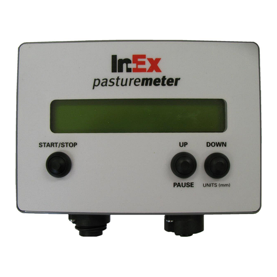
Page 11: The Indicator Console
The Indicator Console This is normally mounted in a convenient position on the front carrier of the ATV. It is connected by cable to the ATVs battery and also by a thick black data cable to the trailed unit. Various functions are shown on the display and the operator has the ability to adjust each of these. - Page 12 • Run the data cable to the rear of ATV and route in carefully to avoid hot surfaces and pinch points • Leave enough data cable free at the rear of the bike to reach the Pasturemeter sled • Removal of the indicator console is the reverse process.
- Page 13 The rear end of the black cable should be attached so that just the plug and 50mm of cable hang down for attachment to the Pasturemeter. Coil excess cable under seat or tie under rear carrier out of the way.
-
Page 14: The Pasturemeter Sled
The Pasturemeter Sled Setting the angle of sled to the ground The angle between the sled and the ground will need to be adjusted to suit the terrain and towing vehicle. Flat pasture with no obstacles will only require a slight angle, but this should be increased when operating on undulating or pugged ground. - Page 15 Adjusting the angle of sled The drawbar position should be set so the front of the sled is slightly raised. A gap of 25mm between the front of the sled skidplate and the ground should suffice for most pasture. Experience will determine the best angle for the terrain being traversed.
- Page 16 Sled & Sensor Assembly. Attach coupling on the sled to the tow-ball on the ATV. Ensure wheels are down in the transport position. Connect sled cable to indicator console cable hanging from rear. Maneuver sled to extreme left and right positions to ensure cable will not foul wheels and not be damaged by hot exhaust pipe or hot exhaust emissions.
-
Page 17: Raising And Lowering The Sled
Raising and Lowering the Sled Grasp draw-bar on one side at Using other hand, raise or position shown and carefully lower the wheels as desired lift off the ground Repeat the operation to raise or lower each side of the sled CAUTION When raising the sled into the transport position, be careful to follow safe lifting practice. -
Page 18: Measure
This section contains: • General Description • Understanding the indicator console • Understanding pasture covers • How the measurement process works • Measuring your first paddock... -
Page 19: General Description
General Description To date, pasture cover measurement is normally performed by one of the following 3 methods. • Visual assessment • Rising Plate Meter • Pasture Probe These methods can either be subjective, time consuming or rely on a limited number of individual measurements per paddock. - Page 20 The Pasture Meter has been designed to measure the height of pasture grass and average the readings. Internal software then converts the averaged readings to kgDM/ha by using a calibration equation that can be changed for different times of the year. Note: The operator is able to set the indicator console to temporarily show pasture height in “mm”...
- Page 21 Understanding the Indicator Console In preparation for use of your Pasture Meter Indicator Console you need to ensure that you have attended to the following: • Made the initial hardware setups for the Pasture Meter Start/Stop Button Used to: 1. Switch unit On/Off (Long Press) 2.
-
Page 22: Understanding Pasture Covers
Understanding Pasture Covers Pasture Cover Equations are used to convert the height of the grass measured into the more useful Pasture Dry Matter, displayed as Kilograms per Hectare (KgDM/Ha). There is more than one pasture cover equation available, and you need to make sure that you enter the correct equation to suit the seasonal growth stage of the grass. -
Page 23: How The Measurement Process Works
How the measurement process works The steps below outline the overall process for obtaining your farm's pasture cover. They will be explained in the remaining sections of this guide. Press START/STOP Button Turn on console Press START/STOP Button while the Set Equation? Adjust Calibration text is displayed. -
Page 24: Measuring Your First Paddock
Measuring your First Paddock Step 1 – Turning the Console ON Press the START/STOP button for approximately 1 second and the console will turn on Step 2 – OPTIONAL – Change equation • The console screen will display Set Equation? briefly •... - Page 25 Step 3 – Measure your paddock • Start measuring? Is displayed on the screen for the first paddock • Lower the sled • Press the START/STOP button to begin measuring • While measuring, the live reading is displayed on the screen For example 01836 KgDM/ha •...
- Page 26 Disconnected Sensor When the Sensor is disconnected from the console, the console will display a Connect Sensor message. If this occurs unexpectedly check cable connection between sensor and console.
-
Page 27: Parts
This section contains: • Exploded parts diagrams • Parts lists... -
Page 28: Exploded Parts Diagrams
Exploded Parts Diagrams 4500-1410 Console Mounting Kit... -
Page 30: Quick Reference
This section contains: • DIY Calibration Method... -
Page 31: Diy Calibration Method Purpose
DIY Calibration Method Purpose Every farm is different in terms of Soil type, pasture type and climate. Pasture measuring devices are calibrated on a regional basis and may not always be representative of your particular farming operation. This DIY Calibration Method will allow you to self calibrate your pasture meter so you can make decisions with confidence on your collected data. -
Page 32: Equation Calculation Steps
Equation Calculation Steps Step 1 - Calculate total and Avg. For columns A & B ➢ Calculate (G) = Sum of Column A (i.e. 25 + 40 + ... = 250) ➢ Calculate (H) = Sum of Column B (i.e. 1200 + 2350 + ... = 7800) ➢... -
Page 33: Understanding The Pasture Calibration Process
Understanding the Pasture Calibration Process Calibration Equations are used to convert the raw sensor measurement, pasture height (reordered in mm), to pasture cover (kgDM/ha). There are several ways to do this; these include comparing your height reading with: o Calibration cuts o Visual assessment o Rising Plate Meter A calibration equation is most commonly expressed as a straight line formula, a straight... - Page 34 • On your console the intercept is referred to as “Constant” • The intercept relates to how much dry matter cannot be read by the sensor (i.e. is below the bottom sensor) • If your calculated intercept = 750 this means: 750 kg DM/ha sits below the bottom sensor and cannot be read When pasture height using the sensor 0 mm there is actually 750 kgDM/ha of pasture residue...
Need help?
Do you have a question about the Pasturemeter and is the answer not in the manual?
Questions and answers