Table of Contents
Advertisement
Quick Links
Advertisement
Table of Contents

Subscribe to Our Youtube Channel
Summary of Contents for BassBoss MFLA-MK3
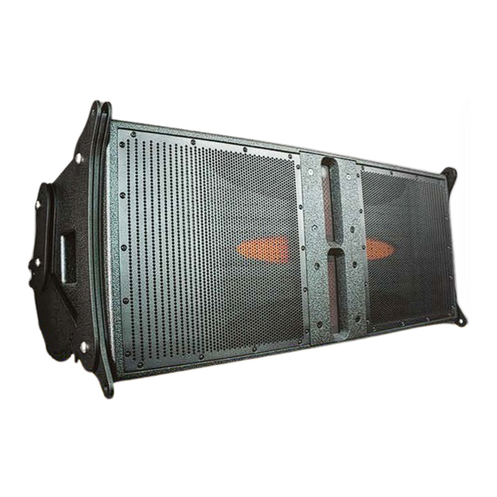
- Page 1 Dual 12” MFLA-MK3 Line Array User Manual...
-
Page 2: Table Of Contents
Este manual está disponible en español en nuestro sitio web en bassboss.com/support The MFLA-MK3 is a dual 12” line array element featuring dual 3” voice coil, 1.4” throat compression drivers, a 3000W Fixed-Point Flyware ensures absolutely consistent box-to-box alignment. The high-frequency output of an array can amplifier and an integrated DSP. Low current draw and light weight relative to their output capacity means you can only remain coherent at higher frequencies if the cabinets cannot move front-to-back once the pins are inserted. The... -
Page 3: Setting Up The Mfla-Mk3 Line Array
Setting up the MFLA-MK3 Line Array 2. Preparing the Next Cabinet (Cab B) - Lock the rear linkage of Cab B in the “Transport” position. - Place Cab B on its back, facing upwards. Using the Rigging System - I nsert the front flyware pins into the “top” linkage position (the double extensions) to The MFLA-MK3 Line Array has recesses on one side and sliders on the other. The sliders are provide a handhold. located at the bottom of the cabinet. The rigging hardware includes single extensions at the 3. Aligning and Stacking Cab B bottom front and double extensions at the top front. - With Cab B facing upwards, bring it to the rear of Cab A. There are two holes just behind and below the pivot point of the cam. These holes line - Align the sliders on the upward-facing Cab B with the grooves on the secured Cab A. up with holes in the cam and are used to lock the cam into specific positions before the - Lift Cab B evenly until about half of it is above the top of Cab A. cabinets are flown or secured. - Rotate the front of Cab B down onto Cab A, keeping the sliders aligned. Bottom of Array Position - Cab B should land with its front approximately halfway back on Cab A. -
Page 4: Setting The Angles
2. Adjusting the Angle - L ifting from both a front and rear point on the spine will allow the pitch angle of the array to - L ift the handle beyond the first pin location. You’ll hear a click as it locks into each be adjusted by shortening or lengthening the supports to the front and rear points. successive angle. - T he frame can also be lifted from any single point along the center spine, with the pitch - Count each click to reduce the angle by 1 degree: angle set by the relationship between the lifting point and the mass-center of the array. - 1st click: 9 degrees 2. Stabilizing Points - 2nd click: 8 degrees - 3rd click: 7 degrees - A dditional points with lower load-bearing capacity are on the side beams. These are for - Continue this way down to 0 degrees. stabilizing the hang or for four-point hangs in installations. - O nce you reach the desired angle, release the handle and insert the pins into the “Linking” hole in the flyware. bassboss.com/mfla 7 MFLA-MK3 Line Array User Manual... -
Page 5: Ground Support
- Up to four MFLA-MK3s can be deployed on a VS21 subwoofer using the VSLA bracket. - T he “Landing” position corresponds to the 1° angle, so if this is the desired angle, transfer - T he VS21 and MFLA-MK3 cabinets have the same width, allowing the MFLA-MK3 tops to the pins directly to the “Linking” position. be deployed above the VS21s using their integrated flyware. - I f a 0° angle is desired, lift the handle on the back of the cabinet and insert the pin into the “Linking” position. 2. Connecting the MFLA-MK3 to the VSLA Bracket - F or angles greater than 1°, lower the array to the point where the desired inter-box angle - T he MFLA-MK3 flyware locks into the VSLA bracket in the same way it locks into other can be set, and insert the pins into the “Linking” position. MFLA-MK3 cabinets or their transport carts. - T he angle of the lowest cabinet can be adjusted as needed, while the cabinets above function as they would in any other deployment. bassboss.com/mfla 9 MFLA-MK3 Line Array User Manual... -
Page 6: Connecting The Array
- Set all input attenuators in all the cabinets to the same level. 2. Removing the Wheels - T he cart’s wheels can be removed, and the cart frame can be used as a base. 3. Ethernet Connections - T he frame can be bolted, clamped, or strapped to a secure platform before stacking the - Each cabinet has two Ethernet ports. array on the frame. Use this method for art-cars and parade floats. - Chain multiple cabinets on the same run for remote control. - R emoving the wheels also allows the base to be used above subwoofers that don’t have - C onnect an Ethernet cable between the first cabinet in the chain and a host computer flat surfaces. running ControlBASS software, either directly or via a router. bassboss.com/mfla 11 MFLA-MK3 Line Array User Manual... -
Page 7: Quick Start Guide
3. Connect the XLR-M connector to additional subs or tops. without degrading the sound quality and without putting components at risk. Before considering using an outboard processor, contact BASSBOSS customer service with your use-case scenario for 4. Connect the mains power and verify the “Ready” LED is lit. -
Page 8: Operation And Controls
The Protect LED also is engaged when the system has been muted via the software. Comm Link: Indicates communication is active on the LAN connection(s). Indicator LEDs, Right Side, Bottom to top: Presets 1-8 - The illuminated LED indicates the corresponding preset is loaded. bassboss.com/mfla 15 MFLA-MK3 Line Array User Manual... -
Page 9: Pre-Installed Onboard Presets
Connect no more than one 5000W or two 2500W subwoofer amplifiers to a single 20A circuit. If you need to share circuits, don’t exceed two BASSBOSS single-driver subwoofers or one double-driver subwoofer, along with one or two top speakers, on the same circuit. -
Page 10: Specifications
BASSBOSS personnel. This warranty does not cover labor other than that authorized and performed by BASSBOSS personnel. Service will be performed upon the return of IP Connections: IP-65 rated signal connections and isolated DSP the failed unit, together with its original sales receipt or other proof of purchase, to BASSBOSS or an Flight Case: Multi-box Touring Cases for up to 5 cabinets. Array Frame (Bumper Bar): Standard Rigging Frame with multiple lifting points Authorized Service Facility. -
Page 11: Safety Information
CRT monitors or magnetic storage media. Never attempt to carry out any operations, modifications or repairs that are not expressly described in this manual. Contact your dealer or BASSBOSS support if the product is not functioning properly. Manufacturer The audio system must comply with current local standards and regulations regarding electrical systems. - Page 12 MFLA-MK3 Dual 12” Line Array Need more assistance? We’re here to help. bassboss.com/support...
Need help?
Do you have a question about the MFLA-MK3 and is the answer not in the manual?
Questions and answers