
Summary of Contents for Aquametro Viscosity VC312
- Page 1 Version: VD 7-475 05.2024 Installation and Operation Manual Viscosity Controller VC312/VC322/VC622...
-
Page 2: Table Of Contents
Content Introduction ..........................3 Liability disclaimer ............................3 Safety precautions ............................3 Receiving and storage requirements ......................4 Application ..........................4 Description of Viscosity Controller ........................ 5 Controller Layout............................6 Controller interface settings .......................... 7 Controller Installation ............................ 8 2.4.1 Mechanical Installation ........................... -
Page 3: Introduction
It is essential that this manual be thoroughly reviewed, with full comprehension of the matters explained herein, before attempting installation and start-up. The materials and workmanship incorporated into the Aquametro Viscosity Control System are designed to provide trouble-free service throughout the equipment lifetime. However, like any rotating equipment,... -
Page 4: Receiving And Storage Requirements
The controllers are preconfigured and designed for a wide variety of control processes with a focus on maritime applications for viscosity control systems. A controller may be part of a complete Aquametro Viscosity Control System. For instructions covering the other components of this system, refer to the separate MBA as supplied with these components. -
Page 5: Description Of Viscosity Controller
TFT display NOTE! Controller settings pre-configured for Aquametro Oil & Marine VCS system (Sensor – AOM Viscomaster / Valve control – AOM steam/thermal oil valve with electrical actuator). Our standard settings are optimized for the AOM VCS system. If another system is used, parameter and settings can be adjusted accordingly. -
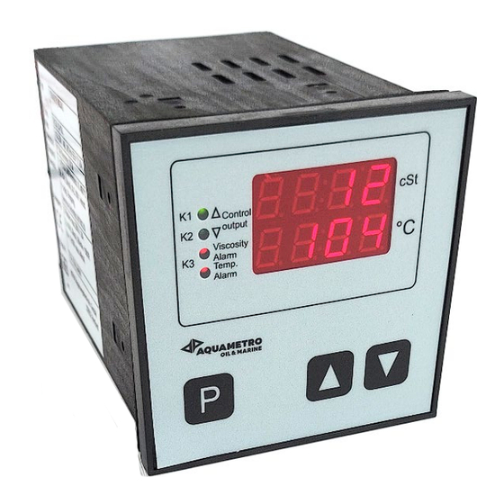
Page 6: Controller Layout
2.2 Controller Layout Controller Type - Display VC322 / VC622 VC312 1-Display for relay function 2-Descriptive text for displayed value 3-Digital value displays 4-Unit of display 5-Key for setpoint and parameter mode 6-Setpoint adjustment VCS – Viscosity Controller... -
Page 7: Controller Interface Settings
2.3 Controller interface settings VC312/322/622 AI1 - Viscosity pre-adjustment 4 to 20 mA / 0 to 50 cSt Analogue input AI2 - Temperature pre-adjustment 4 to 20 mA / 0 to 200 °C VC312/322 1 binary inputs, external voltage 0/24 VDC or potential free contact 0 V resp. -
Page 8: Controller Installation
2.4 Controller Installation 2.4.1 Mechanical Installation Numerous external factors can affect the controller's successful operation. To ensure that your system works correctly, consider the factors covered in this section when designing your installation. Make sure that all electrical safety requirements are met for the environment in which the controller will be installed. -
Page 9: Controller Operation
3 Controller operation Default values Default values for your controller are configured at the factory. The specific values are determined by the options that were specified on the purchase order. These are provided on the configuration sheet that was shipped with your controller. 3.1 Putting into operation Switch on power supply. -
Page 10: Display And Operation Level
3.2 Display and operation level Setpoint value setting Briefly press the button (do not hold) A flashing frame with the description SP shows the activated setpoint level. The upper text display shows the parameter name “SP=” and the adjusted value, the lower text display optionally shows a description text. -
Page 11: Parameter Settings Level
3.4 Parameter settings level Access from the operating level Depending on the controller type, the operating level has to be unlocked with a switch on the back panel of the device. After polling (see instructions for level PARA 1 / 2), a flashing frame with the description PAR1 / PAR2 shows the activated parameter level. -
Page 12: Settings Data Logger
(SP = setpoint, Y=setting variable, Ist * = Actual value channel / EIN1..4 measuring input*) Unit of measurement for corresponding display line (°C / °F / % / bar / mbar / mPas / cSt / Kgm / mm / KPa / L / m /h) Note: no conversion! C 1=ACT.VAL1 Description text for corresponding display line1..4: choose from a... -
Page 13: Configuration Level
Configuration level Access from the operating level Depending on the controller type, the operating level has to be unlocked with a switch on the back panel of the device. Polling: press and hold the button, additionally press the button, hold both buttons for >5 sec, release them after the display reacts: A flashing frame with the description CONF shows the activated parameter level. - Page 14 (* S = Signal 1; S = Signal 2) out2 *Y_S Behaviour of the setting output in the event of measurement line error: rel2(70.) Relay position: "rel1 / rel2 / OFF" rel1(20.) Continuous output: "0...100" (%) bin.Ein Sub-menu for binary input configurations Polling: press the button and hold it >...
- Page 15 Selectable switching functions (depending on version): For setting please refer to configuration level under REL* Switching functions for trailing contacts: Break contact on either side of setpoint LC A (Limit comparator). Relay drops out as deviation increases (Aus = off) Make contact on either side of setpoint LC E (Limit comparator).
-
Page 16: Optimization Control Process (Manually)
3.5 Optimization Control process (manually) An optimum adaptation of the control parameters (P, I, D) is necessary in order to balance an appearing deviation as quickly, non-oscillating and exactly as possible, according to the given operating conditions. Generally these adjustments require a lot of professional knowledge that cannot be replaced by this brief information. -
Page 17: Manual Optimization
3.6 Manual optimization To balance any appearing deviation as quickly a non- oscillation operation conditions of the PID Loop is required. I = Integral action time Tn (min): P = proportional band Xp (%): Lower value = shorter impulse gaps (three-point Lower value = longer impulses (three-point step control), faster balancing step control), more sensitive reaction,... -
Page 18: Maintenance And Repair
Use of wrong Spare Parts Risk of malfunction or damage! Use only original spare parts, supplied by Aquametro Oil & Marine Spare part list and Maintenance instruction may be requested from Aquametro Oil & Marine. 5 Troubleshooting 5.1 Controller problems and recommended actions... -
Page 19: Decommissioning, Dismantling And Disposal
Costs incurred for waste disposal and injury (burns, etc.) due to inadequate declaration and/or cleaning will be charged to the delivering company or the operator. For a device that is sent back to Aquametro Oil & Marine for repair or calibration the following point are an absolute must: Always quote type and serial number when contacting an Aquametro Oil &... -
Page 20: Technical Data
7 Technical data 7.1 Hardware characteristics Body Display Two lines dot matrix / TFT display Keypad 3 Tactile membrane keys Size 96x96x150 Weight 0.5 kg approx. Panel Cut-out B+0,8 / H+0,8 Protection Class IP54 (IP20 Terminals) Environmental Operating temperature Range 0-60°C Operating humidity range <75 %RH (non-condensating) -
Page 21: Electrical Connection Diagrams
7.3 Electrical connection diagrams 7.3.1 Controller type VC312 Controller interface VC312 Controller wiring diagram VC312 VCS – Viscosity Controller... -
Page 22: Controller Type Vc322
7.3.2 Controller type VC322 Controller interface VC322 / VC622 Controller wiring diagram VC322 VCS – Viscosity Controller... -
Page 23: Controller Type Vc622
7.3.3 Controller type VC622 Controller wiring diagram VC622 continuous control VCS – Viscosity Controller... - Page 24 Aquametro Oil & Marine AG Aquametro Oil & Marine GmbH CH-4106 Therwil, Switzerland DE-18119 Rostock, Germany info@aquametro-oil-marine.com info@aquametro-oil-marine.com www.aquametro-oil-marine.com Phone +41 61 725 44 00 Phone +49 381 382 530 00 VCS – Viscosity Controller...
Need help?
Do you have a question about the Viscosity VC312 and is the answer not in the manual?
Questions and answers