Table of Contents
Advertisement
Quick Links
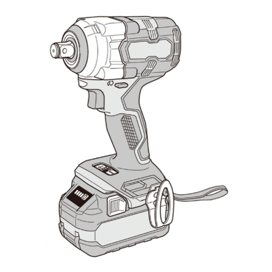
PRODUCT NAME
Cordless Impact Wrench
WR 36DH
Models
WR 18DH
CONTENTS
TROUBLESHOOTING GUIDE ---------------------------------------------------------------------------------------------- 1
REPAIR GUIDE ----------------------------------------------------------------------------------------------------------------- 2
1. Precautions on disassembly and reassembly ------------------------------------------------------------- 2
• Disassembly ----------------------------------------------------------------------------------------------------- 2
• Reassembly ----------------------------------------------------------------------------------------------------- 6
• Type of silicone rubber -------------------------------------------------------------------------------------- 14
• Application of lubricant -------------------------------------------------------------------------------------- 14
• Tightening torque --------------------------------------------------------------------------------------------- 16
• Checking after reassembly --------------------------------------------------------------------------------- 16
• No-load current ----------------------------------------------------------------------------------------------- 16
• Wiring diagram ------------------------------------------------------------------------------------------------ 17
• Compatibility --------------------------------------------------------------------------------------------------- 18
2. Precautions on disassembly and reassembly of the charger --------------------------------------- 18
STANDARD REPAIR TIME (UNIT) SCHEDULES -------------------------------------------------------------------- 19
WR 36DH
CONFIDENTIAL
CONFIDENTIAL
May 2018
Overseas Sales Management Dept.
Jun. 2023
Page
W
Advertisement
Table of Contents

Related Manuals for Koki Holdings WR 36DH

Summary of Contents for Koki Holdings WR 36DH
-
Page 1: Table Of Contents
CONFIDENTIAL CONFIDENTIAL Jun. 2023 May 2018 PRODUCT NAME Cordless Impact Wrench WR 36DH Models WR 18DH CONTENTS Page TROUBLESHOOTING GUIDE ---------------------------------------------------------------------------------------------- 1 REPAIR GUIDE ----------------------------------------------------------------------------------------------------------------- 2 1. Precautions on disassembly and reassembly ------------------------------------------------------------- 2 • Disassembly ----------------------------------------------------------------------------------------------------- 2 • Reassembly ----------------------------------------------------------------------------------------------------- 6 •... -
Page 2: Troubleshooting Guide
• Fuse breakdown • Check for continuity between the • Replace the wiring (WR 36DH only) terminals of the fuse. ass'y. • Check for cracks or wear on the battery • Replace the housing mount of the housing plate set. -
Page 3: Repair Guide
[Bold] numbers in the description below correspond to the item numbers in the parts list and exploded assembly diagram for the Model WR 36DH, and <Bold> numbers to those for the Model WR 18DH. Some abbreviated part names are used in this manual. See the parts list for the full names. - Page 4 4. Disassembly of the hammer assembly (1) Remove Washer (E) [24]<23>, three Needle Rollers [18]<18>, and Idle Gear Set (3 pcs.) [17]<17> from the hammer assembly. (2) Supporting the end face of the Spindle [16]<16>, push down the tabs of the Hammer [12]<12> with a hand press or similar tool to compress the Hammer Spring [15]<15>.
- Page 5 5. Disassembly of the housing plate set (1) Remove the nine Tapping Screws (W/Flange) D4 x 20 [19]<19> to remove the Housing Plate Set [30]<29>. (2) Remove housing (B) of the Housing Plate Set [30]<29> to remove the Strap (Black) [36]<34>. (3) Remove the Inner Cover [27]<26>, Rotor Pinion Ass’y [28]<27>, Wiring Ass’y [38]<36>, and DC-Speed Control Switch [40]<38>...
- Page 6 NOTE: When peeling off silicone rubber, be careful not to damage the connector of the connector cable. • Removal of the wiring ass’y [38]<36> [40]<38> Slowly push down. Internal wire (black) Connector Internal wire (red) Connector cable Connector cable Ribbon cable LED light Fuse (WR 36DH only) Slowly pull out. Terminal support...
-
Page 7: Reassembly
(3) Put the ribbon cable, connector cable, internal wires of the Wiring Ass’y [38]<36>, and fuse (WR 36DH only) between the housing ribs as shown in the figures on page 8. NOTE: Support (D) is provided for the Model WR 18DH instead of the fuse to eliminate the gap. - Page 8 [40]<38> Connector Internal wire (black) Coat the connector with silicone rubber entirely. Internal wire (red) LED light Ribbon cable Fuse (WR 36DH only) Terminal support Check if the contact point is covered with black oxide or plating is peeled off.
- Page 9 Screw boss Put the internal wires of the LED light, connector cable, ribbon cable, fuse (WR 36DH only), and internal wires of the Wiring Ass’y [38]<36> between the two screw bosses. NOTE: Support (D) is provided for the Model WR 18DH...
- Page 10 2. Mounting the rotor pinion ass’y and inner cover (1) Press-fit the Ball Bearing 6901VV-N [25]<24> into the Inner Cover [27]<26>. Insert Damper (B) [26]<25> and Ring Gear [23]<22> aligning with the Inner Cover [27]<26>. (2) Press-fit the Rotor Pinion Ass’y [28]<27> into the Inner Cover [27]<26> as far as it will go. After press- fitting, check that the Rotor Pinion Ass’y [28]<27>...
- Page 11 • Reassembly of the housing plate set (2) Check that half the Wiring Ass’y [38]<36> and half the Rotor Pinion Ass’y [28]<27> are housed in housing (A). Check that half the Inner Cover [27]<26> [27]<26> is housed in housing (A). [38]<36>...
- Page 12 4. Reassembly of the hammer assembly (1) With thirty Steel Balls D3.175 [13]<13> put in the steel ball groove on the Hammer [12]<12>, mount Washer (J) [14]<14>, Hammer Spring [15]<15>, and Spindle [16]<16> to the Hammer [12]<12> in that order. NOTE: Put thirty Steel Balls D3.175 [13]<13>...
- Page 13 5. Mounting the hammer case (1) Mount the Packing [5]<5> to the Inner Cover [27]<26>. NOTE: Align the contour of the Packing [5]<5> with the contour of the Inner Cover [27]<26>. (2) Mount the hammer assembly to the Inner Cover [27]<26> paying attention to the engagement of the Idle Gear Set (3 pcs.) [17]<17>, Ring Gear [23]<22>, and the pinion of the Rotor Pinion Ass’y [28]<27>.
- Page 14 6. Mounting the exterior parts (1) Mount the Front Cap [1]<1> and Protector [2]<2> to the Hammer Case [4]<4>. (2) Insert the Hook [32]<31> into the groove on the side of the Housing Plate Set [30]<29>, and then secure it in place with the Truss Hd. Screw M4 (Black) [31]<30>. NOTE: The Hook [32]<31>...
-
Page 15: Type Of Silicone Rubber
Type of silicone rubber Please purchase the following silicone rubber as necessary. Item Registered part name Net weight Code No. Three Bond 1211 Silicone rubber 100 g 306927 Application of lubricant Apply specified amount of grease to the following portions. Item Registered part name Net weight... - Page 16 MOLUB-ALLOY 777-1 (Code No. 325149) Hammer [12]<12> Washer (J) [14]<14> Contact surface with the Steel Ball Cam groove, sliding portion, and D3.175 [13]<13> (30 pcs.): 0.2 g Tab portion: 0.4 g (One side: 0.2 g) oiled groove: 0.3 g Needle Roller [18]<18> Idle Gear Set [17]<17>...
-
Page 17: Tightening Torque
No-load current • WR 36DH 3.0 ± 1.0 A (39.6 VDC—equivalent to the voltage of a fully charged battery) • WR 18DH 5.0 ± 1.0 A (19.8 VDC—equivalent to the voltage of a fully charged battery) -
Page 18: Wiring Diagram
Put the internal wires of the LED light, connector cable, Two internal wires of the fuse ribbon cable, fuse (WR 36DH only), and internal wires of the Wiring Ass’y [38]<36> between the two screw bosses. NOTE: Support (D) is provided for the Model WR 18DH instead of the fuse. -
Page 19: Compatibility
Compatibility Common parts are used for the Models WR 36DH and WR 18DH except the following parts. Be careful not to make a mistake in removing or mounting the following non-common parts. Part name WR 36DH WR 18DH Hammer Case [4]<4>... -
Page 20: Standard Repair Time (Unit) Schedules
STANDARD REPAIR TIME (UNIT) SCHEDULES Repair Model time 60 min. WR 36DH Hook WR 18DH Housing Plate Set Inner Cover Rotor Pinion Ass’y DC-Speed Control Switch Wiring Ass’y General Assembly Hammer Hammer Case Steel Ball Anvil D3.175 Ring Gear Hammer...
Need help?
Do you have a question about the WR 36DH and is the answer not in the manual?
Questions and answers