Table of Contents
Advertisement
Quick Links
INSTALLATION
AND
OPERATING INSTRUCTIONS
FOR
MW-CBDA SERIES 1W-80-A
COMPACT BI-DIRECTIONAL
AMPLIFIERS
Dekolink Wireless Ltd.;16 Bazel St.Qiryat-Arieh Petah-Tikva Israel, 49510
Tel- 972-3-9180-180; Fax-972-3-
9180
-
190
;
;
Email-marketing@dekolink.com
Web site-
r
page 1 of 12
ev 5
11/
www.dekolink.com
02
Advertisement
Table of Contents

Related Manuals for Elisra Dekolink Wireless MW-CBDA 1W-80-A Series

Summary of Contents for Elisra Dekolink Wireless MW-CBDA 1W-80-A Series
- Page 1 INSTALLATION OPERATING INSTRUCTIONS MW-CBDA SERIES 1W-80-A COMPACT BI-DIRECTIONAL AMPLIFIERS Dekolink Wireless Ltd.;16 Bazel St.Qiryat-Arieh Petah-Tikva Israel, 49510 Tel- 972-3-9180-180; Fax-972-3- 9180 Email-marketing@dekolink.com Web site- page 1 of 12 ev 5 www.dekolink.com...
-
Page 2: Table Of Contents
INSTALLATION & OPERATING INSTRUCTIONS CBDA 1W-80-A COMPACT BI-DIRECTIONAL AMPLIFIERS TABLE OF CONTENTS PARAGRAPH PAGE No BDA OVERVIEW BLOCK DIAGRAM DESCRIPTION STEP ATTENUATOR & RF GAIN & SETTING AGC FUNCTION AGC & GAIN CONTROLS BDA INSTALLATION BASE/DONOR ANTENNA INSTALLATION REMOTE/MOBILE ANTENNA INSTALLATION ANTENNA ISOLATION INSTALLATION STEPS DIAGNOSTICS GUIDE... -
Page 3: Bda Overview
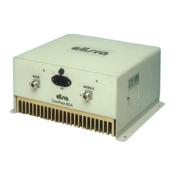
BDA OVERVIEW The Compact Bi-Directional Amplifier (CBDA) assembly provides an exceptional repeater/booster performances to extend the coverage area of radio communications in buildings and RF shielded environments. Features such as high linearity power amplifiers are contributing for the overall improved system linearity performances. The unit is based on a duplexed path configuration, having sharp out of band attenuation for improved isolation between the receiving and transmitting paths. -
Page 4: Step Attenuator & Rf Gain Setting
BASE MOBILE Attenuator Power Monitor Downlink Duplexer Duplexer Power Attenuator Monitor Uplink BDA RF BLOCK DIAGRAM Step Attenuator & RF Gain Setting For proper operation of the BDA; the isolation between the base station antenna and the mobile antenna should exceed the BDA gain by at least 12 dB. If the BDA gain were higher than the isolation between the antennas, oscillation would start and would saturate the amplifier. -
Page 5: Agc Function
AGC FUNCTION The BDA has AGC function on both paths that serve to prevent the saturation of the power amplifier. Their amplifier has a directional coupler and a detector at the output of the high power amplifier to monitor the output power. When a high signal is received the automatic level control detects the amplitude and sends a feedback signal to a voltage variable attenuator which attenuates the signal level so that the output power of the amplifier does not exceed the preset limit. -
Page 6: Bda Installation
BDA INSTALLATION Install the BDA Repeater in a shielded, ventilated and easy to reach area. Use low loss cables to connect antennas to the BDA. Install the BDA close to the service area to improve output power and noise figure. Mount the BDA with RF connecters pointing down. The RF connection is made via two type “N”... -
Page 7: Installation Steps
INST ALLATION STEPS 1. Install all antennas and connect them to the BDA inputs. 2. Open the access windows at the sides of the BDA so that the variable attenuator is reached and the LED is visible. Turn the AGC On. This AGC limits the output power of the BDA. The AGC on the Downlink path guarantees constant downlink... -
Page 8: Diagnostics Guide
DIAGNOSTICS GUIDE The BDA provides long term, carefree operation and requires no periodic maintenance. This section covers possible problems related to the installation environment. RF Faults and RF Power Amplifiers LED Indications: The LEDs on the power amplifier are set to turn on when the transmitted power has reached or exceeded the specified composite power. -
Page 9: Electrical Specifications
ELECTRICAL SPECIFICATIONS Frequency Range (MHz) SEE TABLE Passband Gain @Min attenuation 80 dB nominal ± 1.5 dB typical Passband Ripple Manual Attenuation Range 0 to 30 dB in 2 dB step Noise Figure 6.0 dB max Impedance level 50 ohms V.S.W.R In/Out 1.5 : 1 max AGC Selection... -
Page 10: Environmental Conditions
ENVIRONMENTAL CONDITIONS ° ° Operating temperature - 30 C to + 50 ° ° Storage temperature - 50 C to + 90 MECHANICAL SP CIFICATIONS Size mm(Inch) 265(10.4) x 250(9.8) x140(5.5) RF Connectors N-type Female Weight 8 kg. Approx RF EXPOSURE WARNING In order to satisfy the FCC RF exposure requirements, you must ensure that the installation complies with the following: One antenna is connected via cable that has typical 1~10 dB attenuation (depends on the length... -
Page 11: Mechanical Outline
MECHANICAL OUTLINE Dekolink Wireless Ltd.;16 Bazel St.Qiryat-Arieh Petah-Tikva Israel, 49510 Tel- 972-3-9180-180; Fax-972-3- 9180 Email-marketing@dekolink.com Web site- page 11 of 12 ev 5 www.dekolink.com... -
Page 12: Limited Warranty
DEKOLINK WIRELESS IMITED ARRANTY Dekolink Wireless [Ltd.] (“Dekolink”), manufacturer of this product (the “Product”) warrants to the original purchaser (“Purchaser”) that the Product is free from defects in materials and workmanship for a term that ends on the earlier of twelve (12) months from the date of activation of the Product or fifteen (15) months from the date of shipment of the Product by Dekolink.
Need help?
Do you have a question about the Dekolink Wireless MW-CBDA 1W-80-A Series and is the answer not in the manual?
Questions and answers