Table of Contents
Advertisement
Machine Translated by Google
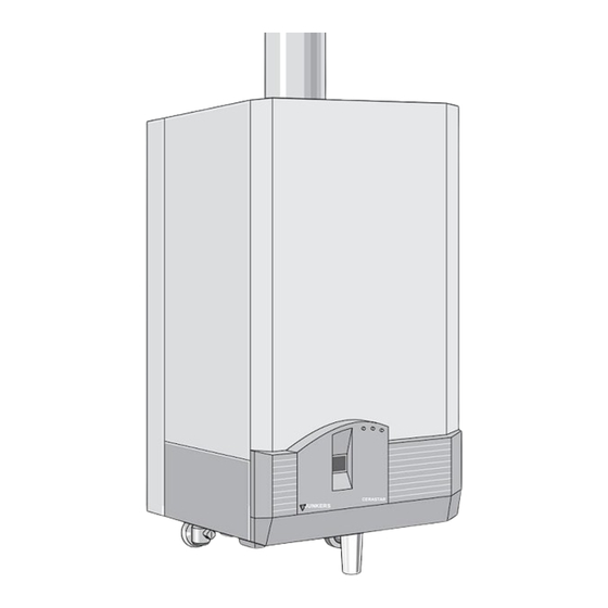
Gas-Kesseltherme
CERASTAR CERAMINI
Low temperature boiler with water-cooled burner
4377-1.1/G ZSR 18-5 KE...
ZSR 24-5 KE...
ZWR 18-5 KE ...
ZWR 24-5 KE ...
If you smell gas:
– Close the gas valve (see page 17, item 172)
– open window,
– do not operate any electrical switches,
– extinguish open flames,
– Immediately call the gas supply company and installation
company from outside.
More safety information on page 2.
CERASTAR
JUNKERS
JUNKERS
4377-2.1/G
ZSR 5/11-5 KE...
• Installation and maintenance may only be carried out by a
approved specialist company.
• The specialist explains to the customer how the device works
and how it is operated.
• Proper functioning is only guaranteed if
if these installation instructions and the operating instructions
are observed.
6 720 604 377
(98.08) PCK
Ceramini
Advertisement
Table of Contents

Subscribe to Our Youtube Channel
Related Manuals for Bosch Thermotechnik JUNKERS ZSR 18-5 KE Series

Summary of Contents for Bosch Thermotechnik JUNKERS ZSR 18-5 KE Series
- Page 1 Machine Translated by Google Gas-Kesseltherme CERASTAR CERAMINI 6 720 604 377 (98.08) PCK Low temperature boiler with water-cooled burner Ceramini JUNKERS CERASTAR JUNKERS 4377-2.1/G ZSR 5/11-5 KE... 4377-1.1/G ZSR 18-5 KE... ZSR 24-5 KE... ZWR 18-5 KE ... ZWR 24-5 KE ... If you smell gas: •...
-
Page 2: Table Of Contents
Machine Translated by Google contents SAFETY INSTRUCTIONS side 1 Device information If you smell exhaust gas: Device description – Switch off the device see page 18, Connection accessories 2.2 – open windows and doors, Type overview 2.3 Design 2.4 – Notify specialist company. Electrical wiring Lineup, Changes Technical data Z..18, 24-5... -
Page 3: Device Information
Machine Translated by Google 1 Device information 2.1 Connection accessories (see price list) • Mounting connection plate EC Type Conformity Declaration: This device complies with the applicable requirements of the • Flush-mounted installation service package European directives 90/396/EEC, • Surface installation service package 92/42/EWG, 73/23/EWG, 89/336/EWG and the in •... - Page 4 Machine Translated by Google 2.3 Structure 33 30 32 34 35 27 26 36.2 36.1 52.1 4 61 317 80 82 88 VSK 443-1.1 R 72 48 47 Picture 3 ZSR 33 30 32 34 35 36.2 36.1 96 95 91 93 52.1 4 61 317...
- Page 5 Machine Translated by Google 3 Measuring connection for nozzle pressure 4 Control box 6 Temperature limiter for heating block 6.1 Flue gas monitoring, flow protection 6.2 Flue gas monitoring, combustion chamber 6.3 Hot water NTC (ZWR) 7 Measuring connection for connection flow pressure 8.1 Manometer 9 Temperature limiter (flow) 11 Reversing line (ZWR) 12 Function line (ZSR) 13 Mounting connection plate...
-
Page 6: Electrical Wiring
Machine Translated by Google 2.4 Electrical wiring 36.2 230V 230V / AC 315 319 1 2 4 7 8 9 L NNsLsLR 328.1 52.1 36.1 4377-5.2S picture 5 4.1 Ignition 161 Jumper transformer 6 300 Coding plug 302 Temperature limiter, heating block 6.1 Connection for protective conductor Flue gas monitoring, flow safeguard 6.2 Flue gas monitoring, combustion chamber 6.3 Hot water NTC... -
Page 7: Technical Data Z
Machine Translated by Google 3 Technical data Z..18, 24-5... Unit ZSR / ZWR 18-5 ... ZSR / ZWR 24-5 ... with ATB1) without ATB1) 18.2 with ATB1) without ATB1) perfomance 17.8 24,3 23,8 rated heat output 20,2 27,0 nominal heat load 10,9 10,7 Smallest heat output... -
Page 8: 3.1 Technical Data Z
Machine Translated by Google 3.1 Technical data Z..5/11-5... Unit ZSR 5/11-5... with ATB1) without ATB1) perfomance 10.9 10,6 rated heat output 12,1 nominal heat load Smallest heat output Smallest heat load 5,5-10,9 5,4-10,6 Heat output adjustable Gas connection value m3 / Erdgas L/LL (HUB = 8.5 kWh/m3 h m3 / Erdgas H (HUB = 9.4 kWh/m3 ) -
Page 9: Site
Machine Translated by Google 4 location contain genes that e.g. B. in solvents, Far ben, adhesives, propellants and household cleaning can be included. installation room The DVGW-TRGI apply to systems up to 50 kW, for If the boiler therme is mounted above the bathtub, LPG appliances the TRF. -
Page 10: Installation
Machine Translated by Google 6 Installation device attachment The screws with accessories are the 6.1 General information device packaging. The location of the holes is shown in Figures 10 and 11. Before installing the boiler boiler, the opinion of the parallel circuit gas supply company and Two or three boiler therms can be combined with... - Page 11 Machine Translated by Google flow noise exhaust duct This can be avoided by installing an overflow valve To avoid corrosion, only exhaust pipes or in the case of two-pipe heating systems by installing a use aluminum. Exhaust pipes tightly closing three-way valve on the furthest radiator Lay according to DVGW-TRGI or TRF.
-
Page 12: Connection Dimensions
Machine Translated by Google 6.2 Connection dimensions min. min. 4 377-10.2 R Picture 10 CERASTAR min. min. 92,5 4 377-11.2 R Picture 11 CERAMINI Legend for Fig. 10 and 11 D 103 flap Z..18-5..110, Z..24-5... 130 13 Mounting connection plate 122 mounting template (accessories) 101 Jacket shell 338 location electric wire from the wall... -
Page 13: Montage
Machine Translated by Google Mounting connection plate, delivery condition Operation of ZSR devices without hot water tank Will the boiler boiler without a hot water tank operated, the bridging arc (278) between to be installed as shown in Fig. 14. The bridging arch is available under accessory no. -
Page 14: Electrical Connection
Machine Translated by Google 6.4 Electrical connection Remove the jacket shell, at CERAMINI The regulation, control and safety devices are fully wired and tested. It just has to the on-site mains connection AC 230 V/50Hz must be established. The hole of the cable bushings no larger select as the cable diameter, otherwise the Splash water protection (IP) no longer guaranteed. -
Page 15: Heating Control Connection
Machine Translated by Google 6.5 Heating control connection The boiler therme can only be operated in conjunction with a JUNKERS controller. Connection of continuous room temperature controller, TR100, 200, TRQ 21.., TRP 31 The connection of the TRP 41/51 is only possible with a controller connection module RAM. picture 20 –... -
Page 16: Connection Locking Switch
Machine Translated by Google 6.9 Connection of a temperature limiter (B2) in pure underfloor heating systems (1-circuit system) – Remove bridge (161) between 8 - 9 4151-49.5S picture 24 – Plug from storage NTC to printed circuit board ken ÿ. 6.7 Connection of an indirectly heated storage tank with storage tank thermostat picture 27... -
Page 17: Commissioning With Factory
Machine Translated by Google 7 Commissioning with factory setting It is essential to comply with the commissioning protocol “9 Commissioning report” page 28, fill out. picture 29 8.1 Pressure gauge – Adjust the pre-pressure of the expansion vessel to the 14 Funnel siphon 15.1 static height of the heating system, see page 21. - Page 18 Machine Translated by Google turn on Hot water only (summer mode) Picture 33 picture 30 In this position, only the hot water supply is activated. The heating is switched off. The control lamp lights up green. The power supply for heating control and timer remains.
- Page 19 Machine Translated by Google DHW temperature storage tank at ZSR After the reset button has been pressed, the flow temperature and For hot water tanks with NTC sensor: the device is in operation. If the fault cannot be eliminated, please call customer service.
- Page 20 Machine Translated by Google Pump blocking protection This automatic function prevents the heating pump from seizing up after a long period of non-use. After each pump switch-off, a time measurement takes place and after 24 hours the pump is switched on for 1 minute. 20 4 377...
-
Page 21: Mechanical Settings
Machine Translated by Google 8 Set the gas boiler to Temperature controller position flow temperature approx. the local plant conditions for heating flow 8.1 Mechanical settings expansion tank The initial pressure of the expansion tank should correspond to the static height of the system. At a maximum heating water flow temperature of 88 C can be the maximum water content (l) of... -
Page 22: Settings On The Bosch Heatronic
Machine Translated by Google 8.2 Settings on the Bosch Heatronic Commissioning report Date of commissioning_____________________ 8.2.1 Increased starting power, service function 9.0 (only for natural gas) Calorific value HuB______kWh/m3 , gas volume______l/min To even under unfavorable operating conditions Low Temp Boiler___, Standard Boiler___ (e.g. -
Page 23: Max. Heating Output, Service Function 5.0
Machine Translated by Google 8.2.2 Max. heating output, service function 5.0 Some gas utilities require one performance-related basic price. It therefore makes sense to set the heating output to the heat requirement. The heating output can be between the smallest Heat output and nominal heat output can be adjusted to the specific heat demand. -
Page 24: Min. Power, Service Function 5.5
Machine Translated by Google 8.2.3 Min. power, service function 5.5 8.2.4 Storage charging capacity, service function 2.3 The storage charging power can be between the smallest The minimum output of the gas boiler Heat output and nominal heat output on the ZSR 5/11-5 is limited at the factory, see technical data. -
Page 25: Max. Flow Temperature, Service Function 2.525
Machine Translated by Google 8.2.5 Max. flow temperature, service function 2.5 The maximum flow temperature can be between 35°C and 88°C. Factory setting is 88°C. Changing the max. flow temperature – Turn the temperature controller for the heating flow to “E”, Figure 52. -
Page 26: Speed Lock, Service Function 2.4
Machine Translated by Google 8.2.6 Pump switching mode, service function 2.2 – Enter the set pump switching mode on the enclosed commissioning report, Figure 44. When a weather-compensated controller is connected, – Press and hold the service button until pump switching mode 3 “[ ]”... -
Page 27: Switching Differential, Service Function 2.6
Machine Translated by Google – Temperature controller for heating flow and hot water to 8.2.9 Type of lower power limitation the originally set values (Austria), service function 5.3 turn. When connecting to a moisture-resistant flue gas collector according to ÖNORM B 8200, version 1, there is when operating the boiler boiler 8.2.8 Switching differential (ÿt), service function 2.6 no restrictions. -
Page 28: Commissioning Report
Machine Translated by Google 9 Commissioning report It is imperative that the enclosed commissioning report, Figure 44, be completed and visible on the device stick on. This simplifies the adjustment considerably in the event of a repair. Picture 65 Reading out the set values of the Bosch Hea tronic read when service function how to read... -
Page 29: Gas Setting
Machine Translated by Google 10 Gas setting According to TRGI Section 8.2, it is not necessary to set the nominal heat output. It must be checked whether the type of gas specified on the type plate corresponds to the type of gas supplied by the gas supplier. Natural gas: Natural gas H units are set and sealed ex works to a Wobbe index of 14.9 kWh/m3 and a connection pressure of 20 mbar. - Page 30 Machine Translated by Google – On the temperature controller for hot water “2.” set len, ie maximum heat output. – Required connection flow pressure for natural gas between 18 and 24 mbar. Under 18 or over 24 mbar, neither an adjustment nor a start-up may take place, the cause must be determined and the error eliminated.
-
Page 31: Conversion To A Different Type Of Gas
Machine Translated by Google 11 Conversion to a different type of gas – For min. specified gas flow rate (l/min) from the table on page 35. Set the gas flow rate using the gas The following conversion kits are available for conversion adjustment screw 64. -
Page 32: Adaptation To The Chimney
Machine Translated by Google For Austria , when connecting to a conventional flue gas 12 Adaptation to the chimney collector, the type of lower power limitation can be The gas boiler is highly efficient and therefore has a low changed, see 8.2.9. flue gas temperature. -
Page 33: Maintenance
Machine Translated by Google 14 Maintenance fuse (6.1) and an exhaust gas monitor on the combustion chamber (6.2). Servicing may only be carried out by an authorized person The exhaust gas monitors are maintenance-free. specialist company. However, we recommend a functional test of the exhaust gas See maintenance contract 6 720 600 919. -
Page 34: Overview Of Error Codes
Machine Translated by Google 15 Overview of error codes Hints Display brief description A2 Exhaust outlet at the combustion chamber. Check the heat exchanger for dirt. A3 Exhaust gas NTC on the flow control has open Check exhaust gas NTC and connection cable and replace if necessary. -
Page 35: Gas Settings
Machine Translated by Google 16 gas settings Nozzle pressure (mbar) Gas flow rate (l/min) Gasart Wobbeindex 0o C, 1013 mbar, kWh / m3 12,2 14,9 25,6 Calorific value 15°C, HuB (kWh/m3 ) 11,1 Calorific value 0 ° C, Ho (kWh / m3) Connection pressure in mbar device Power kW...
Need help?
Do you have a question about the JUNKERS ZSR 18-5 KE Series and is the answer not in the manual?
Questions and answers