Table of Contents
Advertisement
Quick Links
Advertisement
Table of Contents

Related Manuals for MCM Electronics MILLER 400A


Summary of Contents for MCM Electronics MILLER 400A
- Page 1 P a g e M A N 1 6 0 MILLER 400A ANALOG RESISTANCE METER USER’S MANUAL Revised Aug 22, 2018 11640 US Hwy 1 Sebastian, FL 32958 Tel: 1.772.794.9448 ~ Fax: 1.772.589.9072 E-mail: sales@mcmiller.com ~ Web Site: www.mcmiller.com Instruments and Software for the Corrosion Engineer...
-
Page 2: Table Of Contents
P a g e M A N 1 6 0 CONTENTS Page Description ………………………………………………………….. Operating Instructions ……………………………………………… Applications ………………………………………………………… 4-Electrode Applications ..…………………………………… Earth Resistivity Measurement ………………………... Electrolyte (Soil) Box Measurement …………………... 3-Electrode Application ……………………………………… 10 2-Electrode Application ……………………………………… 13 Maintenance & Calibration ………………………………………… 15 11640 US Hwy 1 Sebastian, FL 32958 Tel: 1.772.794.9448 ~ Fax: 1.772.589.9072 E-mail:... -
Page 3: Description
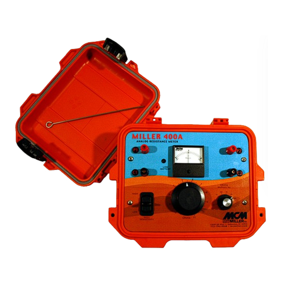
P a g e M A N 1 6 0 DESCRIPTION When combined with appropriate electrodes (pins) and test leads, the MILLER-400A can be used to measure earth resistance or the resistance-to- earth of a buried electrode, such as a ground rod or an anode, for example. Depending on the application, 4-Electrode, 3-Electrode or 2-Electrode, the MILLER-400A can be used to determine the following: •... -
Page 4: Operating Instructions
P a g e M A N 1 6 0 The MILLER-400A runs on a set of replaceable C-size alkaline batteries, so there is no requirement to periodically re-charge the unit or to plug the unit into a power source. Please see the “Maintenance” section for information on how to replace the batteries. -
Page 5: Applications
P a g e M A N 1 6 0 the switch labeled “Ohms Multiply By”) to obtain the resistance value. For example, for a “Balance Dial” setting of 4.5 and a range switch setting of 100Ω, the resistance value is 450Ω 7) Apply the resistance value to the calculation of resistivity using the appropriate formula for your application (see the Applications section below). - Page 6 P a g e M A N 1 6 0 Figure 1 The MILLER-400A can be used in conjunction with M. C. Miller’s 4-lead (color-coded) test reel (catalog # 44700) and four heavy-duty (stainless steel) electrodes (soil pins) – catalog # 44720. The test leads are connected to the MILLER-400A as shown in Figure 1.
- Page 7 P a g e M A N 1 6 0 11640 US Hwy 1 Sebastian, FL 32958 Tel: 1.772.794.9448 ~ Fax: 1.772.589.9072 E-mail: sales@mcmiller.com ~ Web Site: www.mcmiller.com Instruments and Software for the Corrosion Engineer...
- Page 8 P a g e M A N 1 6 0 ρ = 2 π S R where R is the resistance value in ohms as determined using the MILLER- 400A, ρ is the resistivity in ohm.cm, π is the constant 3.1416, and S is the electrode separation in cm.
- Page 9 P a g e M A N 1 6 0 Metric Example (electrode spacing measured in meters): Since there are 100 centimeters in 1 meter, the above formula can be written ρ (Ω.cm) = 2π x 100 x (electrode spacing in meters) x R (ohms) or, ρ...
- Page 10 10 | P a g e M A N 1 6 0 A schematic of the test arrangement is illustrated in Figure 2 below. Figure 2 For this application, the test leads are connected to the MILLER-400A as shown in Figure 2. With this arrangement, the MILLER-400A determines the resistance of the soil sample, or of the liquid that fills the electrolyte box.
-
Page 11: 3-Electrode Application
11 | P a g e M A N 1 6 0 where ρ is the resistivity in ohm.cm, R is the resistance in ohms, A is the cross-sectional area of the current electrodes in cm squared, and L is the separation between the potential electrodes in cm. - Page 12 12 | P a g e M A N 1 6 0 The three electrodes are positioned in a straight line (ideally) as indicated in Figure 3 below. Figure 3 As indicated in Figure 3, a jumper wire is connected between the C1 and P1 terminals on the MILLER-400A and test leads connect the “Potential Electrode”...
- Page 13 13 | P a g e M A N 1 6 0 The magnitude of the resistance reading will be a function of the separation (distance) between the electrode under test and the “Potential Electrode”, with respect to a fixed position for the “Current Electrode”. A characteristic “resistance versus distance”...
-
Page 14: 2-Electrode Application
14 | P a g e M A N 1 6 0 Assuming that a plateau-type region is obtained, the resistance-to-earth value for the electrode under test will be the resistance value on the plot corresponding to the plateau region as illustrated in Figure 4. A general rule-of-thumb, which assumes that the “Current Electrode”... - Page 15 15 | P a g e M A N 1 6 0 Figure 5 As indicated in Figure 5, in this configuration, jumper wires are connected between terminals C1 and P1 and between terminals C2 and P2. In addition, test leads connect one of the electrodes to terminal C1 and the other electrode to terminal C2.
-
Page 16: Maintenance & Calibration
16 | P a g e M A N 1 6 0 The resistance reading determined by the MILLER-400A will be a direct measurement of resistance comprising 2 components; the resistance-to-earth contribution of each electrode (which itself comprises 3 components (see the “3-Electrode Application”... - Page 17 17 | P a g e M A N 1 6 0 11640 US Hwy 1 Sebastian, FL 32958 Tel: 1.772.794.9448 ~ Fax: 1.772.589.9072 E-mail: sales@mcmiller.com ~ Web Site: www.mcmiller.com Instruments and Software for the Corrosion Engineer...
Need help?
Do you have a question about the MILLER 400A and is the answer not in the manual?
Questions and answers