Table of Contents
Advertisement
Quick Links
Advertisement
Table of Contents

Related Manuals for PCE Instruments PCE-EMD 5

Summary of Contents for PCE Instruments PCE-EMD 5
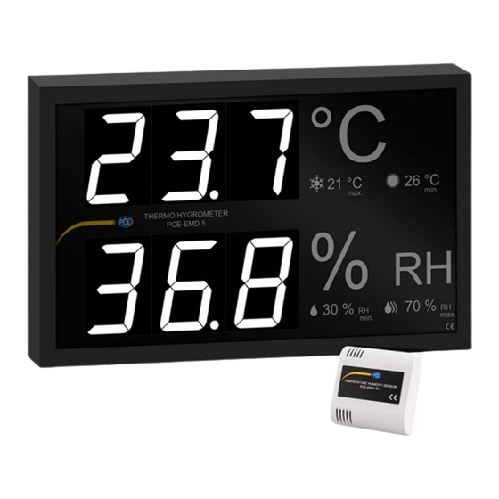
- Page 1 User Manual PCE-EMD 5, PCE-EMD 10 Large Display User manuals in various languages (français, italiano, español, português, nederlands, türk, polski, русский, 中文) can be found by using our product search on: www.pce-instruments.com Last change: 27 May 2024 v1.0 © PCE Instruments...
-
Page 2: Table Of Contents
Wiring diagram for 4 ... 20 mA sensors on the display ..... 6 Sensor connection diagram to PCE-EMD series (display) ....7 Wiring diagram sensor (insulated) ..................8 Wiring diagram sensor (standard) ..................9 Instructions ........................9 Calibration ................... 10 Contact ....................11 10 Disposal ....................11 © PCE Instruments... -
Page 3: Safety Notes
Please read this manual carefully and completely before you use the device for the first time. The device may only be used by qualified personnel and repaired by PCE Instruments personnel. Damage or injuries caused by non-observance of the manual are excluded from our liability and not covered by our warranty. -
Page 4: Specifications
Specifications Temperature PCE-EMD 5 Measurement range 0 ... 50 °C Resolution 0,1 °C Accuracy ±0,5 °C Temperature PCE-EMD 10 Measurement range 32 ... 122 °F Resolution 0,1 °F Accuracy ±0,9 °F Humidity Measurement range 0 ... 99.9 % RH Resolution 0.1 % RH... -
Page 5: Delivery Scope
Delivery scope 1 x large display PCE-EMD series (depending on model) 2 x brackets for wall mounting 1 x user manual Display dimensions © PCE Instruments... -
Page 6: Sensor Dimensions
Sensor dimensions © PCE Instruments... - Page 7 © PCE Instruments...
-
Page 8: Wiring Diagram For 4
Wiring diagram for 4 ... 20 mA sensors on the display © PCE Instruments... -
Page 9: Sensor Connection Diagram To Pce-Emd Series (Display)
Sensor connection diagram to PCE-EMD series (display) Designation Meaning 24 V Supply voltage 24 V 12 V Supply voltage 12 V Connection for humidity Connection for temperature Dimensions © PCE Instruments... -
Page 10: Wiring Diagram Sensor (Insulated)
Wiring diagram sensor (insulated) © PCE Instruments... -
Page 11: Wiring Diagram Sensor (Standard)
The display works completely automatically. The display works as follows: Number of sensors Display 99.9 °C / °F and 99.9 % RH Measured values 2 or more Average of all sensors © PCE Instruments... -
Page 12: Calibration
It is not recommended to change these switches as the sensor is already set appropriately at the factory. Position 1 Position 2 Position 3 Position 4 Correction Calibration switch Signal outputs © PCE Instruments... -
Page 13: Contact
For countries outside the EU, batteries and devices should be disposed of in accordance with your local waste regulations. If you have any questions, please contact PCE Instruments. © PCE Instruments... - Page 14 PCE Instruments contact information Germany France Spain PCE Deutschland GmbH PCE Instruments France EURL PCE Ibérica S.L. Im Langel 26 23, rue de Strasbourg Calle Mula, 8 D-59872 Meschede 67250 Soultz-Sous-Forets 02500 Tobarra (Albacete) Deutschland France España Tel.: +49 (0) 2903 976 99 0 Téléphone: +33 (0) 972 3537 17...
Need help?
Do you have a question about the PCE-EMD 5 and is the answer not in the manual?
Questions and answers