Table of Contents
Advertisement
Advertisement
Table of Contents

Related Manuals for Ranger RCI-29 Base


Summary of Contents for Ranger RCI-29 Base
- Page 1 RCI-29 Base AM/FM/SSB 10 Meter Amateur Base Station User’s Manual...
-
Page 2: Table Of Contents
Table of Contents PAGE Chapter 1 Specifications ................Chapter 2 Introduction ................. Chapter 3 Installation ................. Location and Connection ................Noise Interference ..................Antennas ....................Public Address ..................Chapter 4 Operation ................... Controls and Indicators ................Front Panel ....................Rear Panel Connectors ................Microphone .................... -
Page 3: Chapter 1 Specifications
Chapter 1 Specifications GENERAL Model RCI-29 Base Frequency Range 28.7650 ~ 29.2050 MHz Emission USB, LSB, AM, FM Frequency Control Dual Phase-lock-loop Synthesizer Frequency Tolerance 0.005% Frequency Stability 0.001% Operating Temperature Range C to +50 Microphone Plug-In (4-Pin), 400 Dynamic PTT... - Page 4 Specifications (Continued) RECEIVER AM/CW : 0.50uV for 10dB S+N/N Sensitivity FM : 0.25uV for 12dB S+N/N USB/LSB : 0.15uV for 10dB S+N/N AM/FM Selectivity 50dB at 10 KHz Selectivity 60dB at 4 KHz Image Rejection More than 50dB Rejection More than 80dB SSB/FM/AM 80 dB for 50mV for 10 dB Change in Audio Output Squelch Adjustable-Threshold less than 0.7 uV...
-
Page 5: Chapter 2 Introduction
Chapter 2 Introduction Thank you for your confidence in selecting the RCI-29 Base 10m Band Amateur transceiver. We know you will find your transceiver as exciting as it is practical. Many years of valuable experience designing electronic products are behind our communications systems. -
Page 6: Chapter 3 Installation
Chapter 3 Installation A) Location/Connection The transceiver should be placed in a convenient operating location close to an AC power outlet and the antenna lead in cable(s). The transceiver is attached with the AC power cord set. Proceed as follows to complete all necessary connections to the transceiver. - Page 7 Installation (Continued) 1. Vertical Ground Plane Antenna: These omni-directional antennas can provide optimum performance for DX work due to their low angle of radiation. Ground Plane 2. Directional Beam Antenna: Concentrates power in a narrower beam thereby providing gain and directivity. Directional Beam Antenna D) Remote Speaker The external speaker jack (EXT.
-
Page 8: Public Address
Installation (Continued) NOTE The PHONE jack on the front panel overrides both external and internal speakers. When the plug from a headphone is plugged to the PHONE jack, both internal and external speakers are silenced simultaneously. E) Public address An external 8 Ohms, 4W speaker must be connected to the PA jack located on the rear panel when the transceiver is used as a public address system. -
Page 9: Chapter 4 Operation
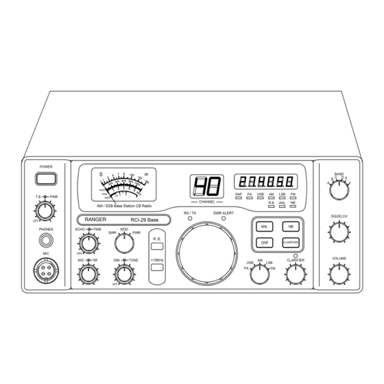
Chapter 4 Operation A) Controls and Indicators i ) Front Panel 1. PHONE JACK: Used to connect headphones for listening. 2. MICROPHONE JACK: Used to connect microphone for voice source. 3. ECHO/TIME CONTROL: The ECHO control is used for echo effect. The TIME control is used to control the intervals of the echo sound. - Page 10 Operation (Continued) 6. SWR/MOD/PWR SWITCH: This switch controls the function of the meter during the transmit mode. In the “SWR” position, the meter indicates the Standing Wave Ratio (SWR) of your antenna(accurate at maximum power output). There are no adjustments because the SWR circuit in this radio calibrates itself automatically.
- Page 11 Operation (Continued) 12. ANL/OFF SWITCH: In the “ANL” position, the Automatic Noise Limiter is activated. 13. MODE SWITCH: This control allows you to select one of the following operating modes: AM/FM/USB/LSB/PA. 14. GNF/OFF SWITCH: This filter de-emphasizes audio high frequency response in order to increase the signal-to-noise ratio of weak signals.
- Page 12 Operation (Continued) 21. PWR CONTROL: This control allow the user to adjust RF power output. 22. POWER ON/OFF CONTROL: Pushing this switch to apply power to the unit. 23. TALKBACK CONTROL: Turn clockwise to activate Talkback circuit. Adjust this knob for desired volume of Talkback. This is used to monitor your own voice.
- Page 13 Operation (Continued) 34. LSB LIGHT: This LED light red when LSB is on. 35. FM LIGHT: This LED light red when FM is on. 36. ANL LIGHT: This LED light red when ANL is on. 37. NB LIGHT: This LED light red when NB is on. 38.
-
Page 14: Ii ) Rear Panel Connectors
Operation (Continued) ii ) Rear Panel Connectors 1. AC POWER CORD: Connect to AC power outlet for ac main supply. Reminder: The internal switching power supply's default AC input voltage setting is 110/120Vac. If the input voltage is 220/240Vac, you need to switch it to 220Vac on the switching power supply before plugging it into the 220~240Vac source. - Page 15 Operation (Continued) 6. PA JACK: This jack is for PA operation. Before operating, you must first connect a PA speaker ( 8 ohms, 4W) to this jack. This jack accept 4 to 8 ohms, 5 watt external speaker. When the 7.
-
Page 16: Microphone
Operation (Continued) B) Microphone The receiver and transmitter are controlled by the push-to-talk switch on the microphone. Press the switch and the transmitter is activated, release switch to receive. When transmitting hold the microphone two inches from the mouth and speak clearly in a normal “voice”. -
Page 17: Operating Procedure To Receiver
Operation (Continued) C) Operating Procedure (Receive Mode) 1. Turn the unit on by setting the POWER SWITCH to ON position. The meters, Frequency Indicator, and Function Indicators will illuminate. 2. Set the MODE SELECTOR switch to desired mode. 3. Set the SQUELCH CONTROL in fully counterclockwise position and adjust the VOLUME control for a comfortable listening level. -
Page 18: Microphone Gain Control
Operation (Continued) E) Microphone Gain Control Start at the 12 o’clock position. Experiment with the control for a setting that provides best transmit audio as reported by other stations. Turning the Mic Gain up too high will cause unnecessary transmit audio distortion, splatter and interference to stations on adjacent frequencies. -
Page 19: Swr Measurement
Operation (Continued) G) SWR Measurement This feature is necessary for proper antenna tuning. A properly cut antenna provides the proper impedance match to the transceiver. A well-matched antenna, as evidenced by low SWR, increases your output power and allows the final amplifier to run cooler and last longer. To measure your antenna’s SWR: 1. - Page 20 Memo - 20 -...
- Page 21 Memo - 21 -...
-
Page 22: Limited Warranty
Ranger warranty repair facility or at the factory. In the event of a defect during the warranty period, Ranger shall, at its option, repair or replace the defective product. Such action shall constitute the purchaser’s exclusive remedy under this warranty. - Page 23 - 23 -...
- Page 24 867 Bowsprit Road Chula Vista, CA 91914 Email:sales@rangerusa.com http://www.rangerusa.com PRINTED IN MALAYSIA P/N:A3825229BB - 24 -...
Need help?
Do you have a question about the RCI-29 Base and is the answer not in the manual?
Questions and answers
why so much white noise on radio