
Summary of Contents for ORBITALSERVICE OWC plus
- Page 1 Instruction manual – OWC plus Orbital welding controller OWC plus Instruction manual - 1 -...
-
Page 2: Table Of Contents
General information Page 3 Safety guidelines Page 3 Application Page 4 Description of functions Page 5 Scope of delivery OWC plus (Original equipment-Standard) Page 6 Views of the controller Page 7 6.1. Right side of the controller Page 7 6.2. -
Page 3: General Information
Instruction manual – OWC plus 1. General information This instruction manual describes the features, functions, operational process and safety-related specifications of the Orbital welding controller OWC plus. Manufacturer: ORBITALSERVICE GmbH Kreuzdelle 13 63872 Heimbuchenthal Germany Tel.: +49-(0)6092 822 94-0 Fax: +49-(0)6092 822 94-09 E-Mail: info@orbitalservice.de... -
Page 4: Application
A new price structure and compatibility with T-Series Power Source make this technology useful for handrail manufacturers and heating engineering. Some special features and Highlights of the OWC plus: a. Compatibility with tachometer controlled welding heads from other manufacturers (AMI, Orbimatic, ESAB, Dimetrics, Magnatech) as well as encoder controlled units (Cajon-Swagelok, Orbitec) b. -
Page 5: Description Of Functions
Instruction manual – OWC plus 3. Description of functions The Orbital welding controller is connected to the inverter power source T – Series (Lorch Company) through a digital cable (CanBus – LorchNet). This connection ensures precision orbital welding with a high quality standard industrial welding machine. -
Page 6: Scope Of Delivery Owc Plus (Original Equipment-Standard)
Instruction manual – OWC plus 3. Scope of delivery OWC plus (original equipment-Standard) The scope of delivery for the controller includes: mounting sheet with holder and screws for the power source handle, a 230 V power cord, gas hose with quick-connect and a LorchNet cable between power source and controller. -
Page 7: Views Of The Controller
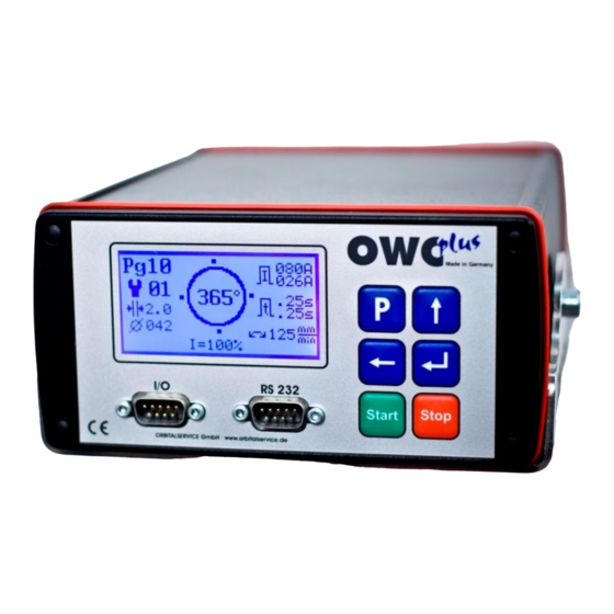
Instruction manual – OWC plus 4. Views of the controller 6. 1. Right side Illuminated graphic display to show all relevant information Robust aluminium die-casting housing Interfaces for data transfer, dokumentation, software update, etc. Plastic foil keyboard for comfortable operation The controller is mounted on a steel sheet and screwed with 2 M6 hex socket screws. -
Page 8: Back Side Of The Controller
Instruction manual – OWC plus 6. 2. Back side ON-OFF-switcher with power cord input, fuse compartment (2 units, 5x20 mm, 1A) and internal network filter Gas input from cylinder Gas output to the welding machine Amphenol C016 flange input for motor cable... - Page 9 Instruction manual – OWC plus Pink LorchNet cable and red gas connection hose with quick-connector between two units are easily recognizable. When the operator releases two gas connectors, the unit can be carried comfortably on a belt over a shoulder.
-
Page 10: Orbital Setting Software" In The Power Source
50 ms. The units of the Orbitalservice GmbH are supplied with the following settings: 1. C1 (OFF) 2. C2 (ON-gas cooled torch / welding head, OFF-water cooled) 3. -
Page 11: Operation
Instruction manual – OWC plus 8. Operation 8. 1. Display buttons and their functions „P-button“ is a program button. This button can be used to enter into various submenus. The button has different functions in different menus. „Up arrow button“ is used to proceed through the menus. -
Page 12: Welding Display (Main Display)
Instruction manual – OWC plus The welding process can be started only when this display is shown. This display has a variety of stored information. Program place (Pg01). 99 places for the controlling are available Rotation welding up to 365° in 4 equal sectors (Levels) -
Page 13: P-Button", Its Functions And Displays
Instruction manual – OWC plus 8. 3. „P-button“, its functions and displays The „P-button“ is used to enter into different menu displays. These menus are always easy-to- understand. There is no need to translate it into different languages. The symbol with a thick,... -
Page 14: Enter-Button", Its Functions And Displays
Instruction manual – OWC plus 8. 4. „Enter-button“, its functions and displays The „Enter-button“ is used to enter into different menu displays. These menus are always easy- to-understand. There is no need to translate it into different languages The symbol with a thick,... -
Page 15: Welding Programming
Instruction manual – OWC plus 9. Welding programming 9.1. Help function (automatic programming) The controller can provide first welding programs even for not very well versed users. For this purpose the software of the controller has some yearly proved basic calculations suggested by other manufacturers. - Page 16 Instruction manual – OWC plus Press 100-interval. Press 10-interval. Press 5 times Press Press 3 times Press - 16 -...
- Page 17 Instruction manual – OWC plus Press Press Press 5 times Press The first weld head is OWH-76. Press Press - 17 -...
-
Page 18: Test Run (Welding Without Arc)
Instruction manual – OWC plus Continuous or stepped rotational The welding program is ready! velocity (stepped burner) Press There is a logic in the program: If the wall thickness is < 2,5 mm, the program suggests a cont. rotational velocity, and for heavy wall thickness –... - Page 19 Instruction manual – OWC plus Symbol „test run“ is activated (highlighted in Press black). Press Symbol „test run“ A good visual control of the rotation (circular path Press with rotation degree and actually measured velocity down to the right) Note: During the test run the gas pre-flow and after-flow time as well as weld pool time are not used.
-
Page 20: Gas Flow Set-Up And Check
Instruction manual – OWC plus 9. 3. Gas flow set-up and check The gas flow shall be checked before the welding process is started. The controller is supplemented with a magnetically inductive gas flow sensor to prevent welding without gas as it can lead to defective welded joints and weld heads, especially in closed construction. -
Page 21: Welding Process
Instruction manual – OWC plus The test for the water-cooled unit can be carried out in the same way. 9. 4. Welding process Press Gas pre-flow time Spark procedure Weld pool time This symbol can be seen only for a... -
Page 22: Parameter Alteration After Welding
Instruction manual – OWC plus The welding is over Stand-by display Gas after-flow time 10. Parameter alteration after the welding 10. 1. Percentage alteration of the power parameter The percentage alteration of the power parameter is the most common option. The operator detects the insufficient root formation after the welding. - Page 23 Instruction manual – OWC plus Hold the button pressed until Press 120% appears All parameters of the current (in all 4 sectors) increase by 20%. - 23 -...
-
Page 24: Parameter Alteration (Power, Pulse Time, Velocity)
Instruction manual – OWC plus 10. 2. Parameter alteration (current, pulse time, velocity) This symbol shows the following international abbreviations: Current Velocity Time It is possible to enter manually into the program suggested and calculated by the controller, overwrite and alter it. Some things have been simplified to support the operator. - Page 25 Instruction manual – OWC plus Press Press Press Press Press Press - 25 -...
- Page 26 Instruction manual – OWC plus Press Press Press Press Press Press Note: button can be used to navigate forward only after the total magnitude is highlighted in black. - 26 -...
- Page 27 Instruction manual – OWC plus Press Press Press Press Press Note: The pulse times have been increased by 100 ms and we enter the sector 4 to reduce the high current by 4 A! - 27 -...
- Page 28 Instruction manual – OWC plus Press Press Press Press Press Press - 28 -...
- Page 29 Instruction manual – OWC plus Press Press Press Hold the button pressed until 7 appears Press Press - 29 -...
- Page 30 Instruction manual – OWC plus All alterations are made. Press Have you noticed it? The controller has an intelligent operator guidance system. If you want to enter into separate sectors to alter specific parameters, you will get a program support providing orbital welder-newcomers with time-saving operation and protection from programming errors.
-
Page 31: Frame Parameters
Instruction manual – OWC plus Sector 1 after alteration (pulse time) Sector 2 after alteration (pulse time) 10. 3. Frame parameters The frame parameters are parameters required for the whole welding process. You can see it visually at the picture on the right. These parameters are given for a welding only once. - Page 32 Instruction manual – OWC plus After the activation of the cold wire the following adjustable parameters will be displayed: Activate the cold wire with button Wire delay (1.000 sec – 50.000 sec) Wire return (1.000 sec – 50.000 sec) Press...
- Page 33 Instruction manual – OWC plus The alteration of individual parameters can be made in the same order. Press the button to enter into the submenu, - set of parameters. Here you can navigate forward with the button. The parameters can be changed with .
- Page 34 Instruction manual – OWC plus Alteration of downslope Press Alteration of gas after-flow time Activation of pulsed current. (Standard). It can be changed by Rotation of the welding unit. It can be Continuous or pulsed rotation of the welding unit.
- Page 35 Instruction manual – OWC plus Stepped-mode is activated Press Additional wire is activated Press Wire delay during the weld pool time (Hold-up time) of the weld head before rotation starts. Press - 35 -...
- Page 36 Instruction manual – OWC plus Press This frame parameter menu has the following settings: activated pulsed current (standard), pulsed rotation (stepped-mode, stepped burner) and additional filler material. - 36 -...
-
Page 37: Parameter Increase/Decrease During The Welding Process
Instruction manual – OWC plus 11. Parameter increase / decrease during the welding procedure During the welding the percentage wire velocity and power can be changed and saved by means of 2-level remote control RC plus (for further information please see chapter Remote Control –... - Page 38 Instruction manual – OWC plus Alter Press by pressing then Press the button to return into the main menu. Alteration during the welding: The current magnitude in all sectors The wire parameters in all sectors have has increased by 25%.
-
Page 39: Avc (Arc Voltage Control)
Instruction manual – OWC plus 10.3.1 AVC (Arc Voltage Control) Press Press 2 x Press Press 7x or 1x Opens a additional menu with more frame parameters (tack, additional cold wire, AVC, OSC) Press 2x Press - 39 -... - Page 40 Instruction manual – OWC plus AVC (arc voltage control) Press Press AVC (arc voltage control) enabled Press Can be changed with Changes the distance of the AVC welding Press electrode (equal to the arc voltage in volt) - 40 -...
- Page 41 Instruction manual – OWC plus Regulating sensitivity (time Press interval/traversing distance): First digit corresponds to time interval, second digit corresponds to traversing ditance (stroke) per time interval AVC retreat in mm/second: During the lowering time from less than 30A the...
-
Page 42: Osc (Oscillation)
Instruction manual – OWC plus 10.3.2 OSC (Oscillation) Press Press 2x Press Press 7x or press 1x Opens a additional menu with more frame parameters (tack, additional cold Press 3x wire, AVC, OSC) - 42 -... - Page 43 Instruction manual – OWC plus Press OSC (oscillation) Press Press OSC (oscillation) enabled Press Can be changed wiith OSC oscillation speed: The higher the Press value, the faster the torch is oscillating. - 43 -...
- Page 44 Instruction manual – OWC plus OSC pendulum distance (espacially for the inal pass): Entered value is the Press distance from the weld centre to the left or right side. Value will be reset to 0 if is enabled. Flank time: Value corresponds to the...
- Page 45 Instruction manual – OWC plus OSC automatic teaching enabled (especially Automatic teaching (especially for for root pass): The weld centre will be middle pass): Automatic approaching automatically approached without the weld centre depending on the OSC dependence on the OSC edge distance.
- Page 46 Instruction manual – OWC plus OSC syncronisation: Flanks will be welded with high current and high current time, if function Press enabled. The distance until next flank (with OSC pendulum speed) will be welded with basic current. In this case the in advanced entered values will be ignored in the OSC flank time at welding.
-
Page 47: Saving And Percentage Alteration Of The Welding Program
Instruction manual – OWC plus 12. Saving and percentage alteration of the welding program You can save all alterations by pressing . The same is applicable to the parameters changed by 13. Welding program information - 47 -... -
Page 48: Printing
Instruction manual – OWC plus The operator can give a name to a A variety of numbers, letters and symbols are program or procedure and it will available in this menu. appear in print. Please use the buttons to enter the required parameter and to navigate forward. - Page 49 Instruction manual – OWC plus The last welding program with target and actual parameters will be printed Press The target and actual parameters will be printed automatically after the welding. - 49 -...
-
Page 50: Documentation
Instruction manual – OWC plus 15. Documentation The controller is designed to store up to 250 welding parameter sets with relevant information. These data sets can be displayed, activated, printed, saved (PC- documentation) or deleted. Press Press The „169“ dataset display Press . - Page 51 Instruction manual – OWC plus Are you going to delete all documentation in the Press controller? If NO, press If Yes, press Delete process Press Press to copy data to the external memory medium (RS 232-Dongle- Orbitalservice GmbH) - 51 -...
-
Page 52: Other Functions Of The „P-Button
Instruction manual – OWC plus 16. Other functions of „P-Button“ Thus, you have got the most important information regarding the welding procedure (assignment, alteration, printing and saving of the welding programs) and we would like to acquaint you with some additional functions of the P-button. - Page 53 Instruction manual – OWC plus Press If this is the required program, please press Define the welding unit used for If the welding unit is not suitable for this application, this warning message with a signal tone will be displayed. Press the Stop-button to...
-
Page 54: Delete A Program
Instruction manual – OWC plus 16. 3. Delete a program Press If NO, press , if YES, press Press 16. 4. Internal program copy Press Enter the number, and press - 54 -... -
Page 55: External Program Copy
Instruction manual – OWC plus Press Press 16. 5. External program copy Press Enter the number, and press Enter the number, and press Press - 55 -... -
Page 56: Program Copy From The External Memory Medium (99 Memory Storage Space)
Instruction manual – OWC plus Press Press 16. 6. Program copy from the external memory medium (memory capacity: 99 places) Press Enter the number, and press Press Enter a weld head, and press - 56 -... -
Page 57: Memory Formatting
Instruction manual – OWC plus This warning message will appear if controller finds internal description for this program. Press STOP to return, and OK to rewrite. 16. 7. Memory formatting Plug the memory into the RS 232 interface and press A formatted memory can be applied for various functions. -
Page 58: Test Run- Welding (See Chapter 9.2.)
Instruction manual – OWC plus 17. Test run – Welding (see chapter 9.2.) 18. Gas and water test (see chapter 9.3.) 19. MAX/MIN – Monitoring limits Press Press Percentage current monitoring Press Min. arc voltage Press - 58 -... - Page 59 Instruction manual – OWC plus Max. arc voltage Press Percentage velocity monitoring (for Stepped-mode 50%) Press Freely adjustable spark current (Recommendation: 25 A) Press - 59 -...
- Page 60 Instruction manual – OWC plus Gas flow monitoring Press Rest oxygen content before welding Press Rest oxygen content during the welding - 60 -...
-
Page 61: System Settings
Instruction manual – OWC plus 20. System settings Press Press Date and time set-up option Press Stepless contrast control Press - 61 -... - Page 62 Instruction manual – OWC plus 11 – Coil and uncoil is activated Automatic coil and uncoil of the tube packet (open-frame weld heads) 00 – no coil and uncoil White signal tones (button click and buzzer are deactivated) Press Signal tone...
-
Page 63: Counter
Instruction manual – OWC plus 21. Counter - 63 -... -
Page 64: Administrator
Instruction manual – OWC plus 22. Administrator Press This information area is reserved for the manufacturer and service partners. Here you can find all welding units, update your software and language files and localize errors using various integrated diagnostics and monitoring programs. - Page 65 Instruction manual – OWC plus Yellow LED, indicates activated Shift-button) 1. Level: Start and Stop the downslope 1. Level: Stop 2. Level (with Shift): Test run 1. Level: rotate to the right 2. Level (with Shift): raise the current during the welding 1.
-
Page 66: Technical Data
Instruction manual – OWC plus 24. Technical data Mechanic: Dimentions (LxWXH) 240 mm x 170 mm x 90 mm Weight 2,2 kg Degree of protection IP 40 at 20 °C General data (electrical engineering) 100 – 240 V, 47 – 63 Hz...
Need help?
Do you have a question about the OWC plus and is the answer not in the manual?
Questions and answers