Advertisement
Table of Contents
Advertisement
Table of Contents

Subscribe to Our Youtube Channel
Summary of Contents for WESTENDORF V-2241414031
- Page 1 2241414031...
- Page 3 1 OF 5 DR. BY: DATE: 1/5/2001 DATE: PAGE: REF. PART NO. DESCRIPTION QTY. REMOTE 2J JOYSTICK RM-22 72" CABLE RM-93 VALVE ATTACH KIT AHS0420012 ALLEN HEAD SCREW 1/4" X 3/4" WESTENDORF MFG. CO. INC. ONAWA, IOWA 51040 PHONE (712) 423-2762...
- Page 4 V-1241400000 ASSEMBLY INSTRUCTIONS DATE: 1/5/2001 RN: 0 2 OF 5 PAGE: STEP: 1 READ OPERATOR'S MANUAL OPERATOR'S MANUAL STEP: 1 A) Read through the "Operator's Manual" and "Assembly Instructions" before starting. The more familiar you are with the instructions and operation of the loader the easier it will be to attach the joystick and connect it to the valve.
- Page 5 V-1241400000 ASSEMBLY INSTRUCTIONS DATE: 1/5/2001 RN: 0 3 OF 5 PAGE: STEP: 3 ATTACH JOYSTICK SLEEVE CLAMP BOLT LOCK WASHER CABLE JOYSTICK STEP: 3 (illustration shows bottom of joystick) A) Insert the cable into the joystick and secure in place with the sleeve clamp bolt, lock washer and nut removed previously.
- Page 6 V-1241400000 ASSEMBLY INSTRUCTIONS DATE: 1/5/2001 RN: 0 4 OF 5 PAGE: STEP: 7 ADJUST CABLES ALLEN HEAD SCREW 3/4" JAM NUT BONNET STEP: 7 (illustration shows left spool; repeat step for right spool) A) Adjust the joystick control by turning the bonnet to loosen or tighten the cable. Watch the joystick while turning the bonnets making sure the joystick stays centered.
- Page 7 V-1241400000 ASSEMBLY INSTRUCTIONS DATE: 1/5/2001 RN: 0 5 OF 5 PAGE: STEP: 9 RECOMMENDED OPERATION LEFT TO ROLL BACK FORWARD TO LOWER (FLOAT POSITION) BACK TO LIFT RIGHT TO DUMP STEP: 9 A) These are the recommended operating positions for the joystick control. NOTE: When hooking up the loader you may need to move the hoses around until the loader operates the way you want it to.
- Page 8 V-0240014000 DATE: 8/13/08 DR. BY: GJS DATE: PAGE: 1 OF 4 REF # PART # DESCRIPTION PF-OS08 SWIVEL ADAPTER PF-OS0806 SWIVEL ADAPTER READ THESE INSTRUCTIONS THOROUGHLY WESTENDORF MFG. CO. INC. ONAWA, IOWA 51040 PHONE (712) 423-2762 www.loaders.com...
- Page 9 ASSEMBLY INSTRUCTIONS V-0240014000 DATE: 8/13/08 DR. BY: GJS DATE: PAGE: 2 OF 4 ATTACH SWIVELS REF # DESCRIPTION VALVE 90° SWIVEL ELBOW POWER BEYOND ADAPTER SWIVEL ADAPTER HEX HEAD PLUG O-RING HEX HEAD PLUG STEP 1: A) Attach four 3/4" X 3/8" swivel adapters to the valve, as shown B) WITHOUT POWER BEYOND, Remove the power beyond adapter from the valve, and replace it with the hex head plug provided, as shown.
- Page 10 MOUNTING INSTRUCTIONS V-0240014000 DATE: 8/13/08 DR. BY: GJS DATE: PAGE: 3 OF 4 VALVE HOSE HOOKUP LOADER HOSES LIFT CYLINDER RAM END BARREL END BUCKET CYLINDER BARREL END RAM END NOTE: USE THREAD SEALANT WHEN CONNECTING THE HOSES "B" "C" "A"...
- Page 11 MOUNTING INSTRUCTIONS V-0240014000 DATE: 8/13/08 DR. BY: GJS DATE: PAGE: 4 OF 4 RECOMMENDED OPERATION "FORWARD" TO LOWER (FLOAT POSITION) "LEFT" TO ROLL BACK "RIGHT" TO DUMP "BACK" TO LIFT STEP 4: A) These are recommended operating positions for the joystick control. NOTE: When hooking up the loader you may need to move the hoses around until the loader operates the way you want it to.
- Page 12 VP-1-02 CONTROL STAND BASE HHS0518016 5/16" X 1" BOLT HHS0518064 5/16" X 4" BOLT LWM05 5/16" LOCK WASHER HFN0518 5/16" NUT HTN0518 5/16" LOCK NUT READ THESE INSTRUCTIONS THOROUGHLY WESTENDORF MFG. CO. INC. ONAWA, IOWA 51040 PHONE (712) 423-2762 www.loaders.com...
- Page 13 A) Choose a convenient and comfortable place to mount the joystick control. The joystick control is shown mounted on the Westendorf control stand however you may choose to mount the control along the side of the cab, in the console, or some other convenient spot.
-
Page 14: Valve Plate
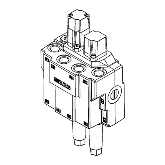
MOUNTING INSTRUCTIONS V-0000000031 DATE: 07/07/21 DR. BY: STR RN: 1 DATE: PAGE: 3 OF 7 ATTACH JOYSTICK 5/16" LOCK NUT JOYSTICK CONTROL STAND 5/16" X 4" BOLT A) Attach the joystick to the control stand, as shown, using three 5/16" X 4" bolts and lock nuts provided. - Page 15 ASSEMBLY INSTRUCTIONS V-0000000031 DATE: 07/07/21 DR. BY: STR RN: 1 DATE: PAGE: 4 OF 7 ATTACH VALVE 2 SPOOL PRECISION VALVE ONLY VALVE VALVE COVER BRACKET VALVE PLATE 8mm X 20mm - 1.25p BOLT A) Attach the valve and the valve cover bracket to the valve plate, as shown, using four 8mm X 20mm - 1.25p bolts provided.
-
Page 16: 5/16" X 1" Bolt
ASSEMBLY INSTRUCTIONS V-0000000031 DATE: 07/07/21 DR. BY: STR RN: 1 DATE: PAGE: 5 OF 7 ATTACH VALVE PLATE 2 SPOOL WITH ELECTRIC 3rd FUNCTION VALVES 2 SPOOL WITH ELECTRIC 3rd AND VALVE ASSEMBLY 4th FUNCTION VALVES 5/16" NUT 5/16" LOCK WASHER VALVE MOUNTING BRACKET VALVE PLATE 5/16"... - Page 17 ASSEMBLY INSTRUCTIONS V-0000000031 DATE: 07/07/21 DR. BY: STR RN: 1 DATE: PAGE: 6 OF 7 ATTACH VALVE 2 SPOOL PRECISION VALVE ONLY VALVE VALVE STAND PIPE VALVE PLATE SET SCREW (HIDDEN) A) Attach the valve plate to the valve stand pipe, as shown, by sliding the pipe into the bushing on the bottom of the valve plate and tightening the set screw.
- Page 18 ASSEMBLY INSTRUCTIONS V-0000000031 DATE: 07/07/21 DR. BY: STR RN: 1 DATE: PAGE: 7 OF 7 ATTACH VALVE 2 SPOOL PRECISION INLINE WITH LEVEL UP ADDED ONLY VALVE STAND PIPE SET SCREW (HIDDEN) VALVE PLATE (HIDDEN) A) Attach the valve plate to the valve stand pipe, as shown, by sliding the pipe into the bushing on the bottom of the valve plate and tightening the set screw.
Need help?
Do you have a question about the V-2241414031 and is the answer not in the manual?
Questions and answers