Table of Contents
Advertisement
Available languages
Available languages
Quick Links
Advertisement
Table of Contents

Summary of Contents for MISTER MENUISERIE MOTORISATIONPLUS SPRINT400
- Page 1 Instructions et avertissements pour l’installation et l’usage Instructions and warnings for installation and use Instruções e advertências para a instalação e utilização SPRINT400 Motoreducteur pour coulissants Gear-motor for sliding gates Motorredutores para portoes de correr...
-
Page 2: Images
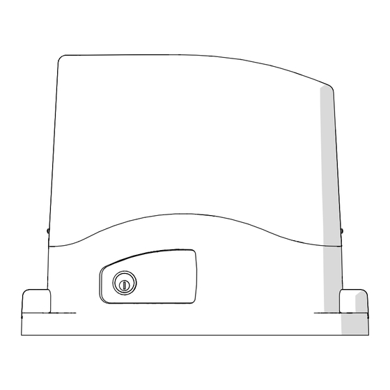
IMAGES Fig. 1 FR - Description du produit EN - Product description PT - Descrição do produto Fig. 2 FR - Installation type EN - Typical Installation PT - Instalação típica Fig. 3 FR - Installation EN - Installing PT - Instalação... - Page 3 Fig. 4 FR - Fixation EN - Fixing PT - Fixação Fig. 5 FR - Pose de la crémaillère EN - Rack assembling PT - Fixação da cremalheira 90mm Fig. 6 FR - Fixation des dispositifs de fin de course EN - Limit switch fixing PT - Fixação dos fins de curso...
- Page 4 Fig. 7 FR - Déverrouillage d’urgence EN - Emergency unblocking PT - Desbloqueio de emergência...
-
Page 5: Table Of Contents
SOMMAIRE Images page 2 Avertissements pour la sécurité page 6 Introduction au produit page 8 Description du produit page 8 Modèle et caractéristiques techniques page 8 Description de la logique de commande page 8 Description des branchements page 9 Modèles et caractéristiques techniques de la logique de commande page 9 Liste des câbles nécessaires page 10... - Page 6 1 - AVERTISSEMENTS POUR LA SÉCURITÉ vérifier que les dispositifs achetés sont suffisants pour ATTENTION ! garantir la sécurité de l’installation et son bon fonction- INSTRUCTIONS ORIGINALES – importantes consi- nement; gnes de sécurité. Il est important, pour la sécurité des personnes, de respecter les consignes de sécu- effectuer l’analyse des risques, qui doit aussi compren- rité...
- Page 7 tous les dispositifs doivent être raccordés à une ligne d’ali- est nécessaire. mentation électrique avec mise à la terre de sécurité; ATTENTION le produit ne peut pas être considéré comme un système Le poids du système d'automatisation étant de protection efficace contre l’intrusion. Si vous souhai- supérieur à...
-
Page 8: Introduction Au Produit
2 - INTRODUCTION AU PRODUIT 2.1 - Description du produit SPRINT400 est un motoréducteur conçu et construit pour être utilisé poids pour le portail. Toute autre utilisation est considérée comme sur des portails coulissants. Le paragraphe 2.2 indique les limites de abusive et est donc interdite. -
Page 9: Description Des Branchements
2.4 - Description des branchements SHIELD STOP OPEN CLOSE PAR POWER SUPPLY 1- Alimentation moteur (M+ et M-) 12- Connecteur pour chargeur de batterie KBP/KBPN 2- Connecteur d’alimentation du transformateur 13- Fusible à retardement de 1,6 AT 3- Connexion de lumière clignotante, lumière de courtoisie, 14- Écran de fonction à... -
Page 10: Liste Des Câbles Nécessaires
SPÉCIFICATIONS TECHNIQUES CE24CNC Alimentation électrique 24 VAC (+10% -15%) 50/60 Hz Puissance maximal moteur 200 W Courant maximal sortie 24VCA 200 mA (24 VAC) Courant maximal sortie PHPOW 200 mA (24 VDC non régulés) Puissance maximale sortie FLASH 15 W (24 VDC) Puissance maximale sortie LED 15 W (24 VDC) Puissance maximale pour la sortie ‘IND/... -
Page 11: Installation Du Produit
4 - INSTALLATION DU PRODUIT 4.1 - Installation Respecter les dimensions d’encombrement pour l’ancrage au sol ATTENTION ! de la plaque de base au moyen de 4 chevilles expansibles (fig.3) ou L’installateur doit vérifier que la plage de températures indi- la noyer dans une coulée de béton (fig.3). -
Page 12: Branchements Électriques
4.6 - Branchements électriques Avant d’effectuer les branchements, vérifier que la logique de commande n’est pas sous tension ATTENTION ! CONNECTEUR MOTEUR DIP SWITCH Sur ON, il désactive les entrées EDGE, PH1, PH2 Bornier des branchements d’alimentation Évite de devoir shunter les entrées sur le bornier. Alimentation du moteur Alimentation du moteur NE PAS UTILISER... - Page 13 CONNEXIONS ÉLECTRIQUES POUR PHOTO1 ET PHOTO2 CONNECTEURS DE DISPOSITIFS DE SÉCURITÉ ET DE CONTRÔLE 24 VAC Alimentation accessoires 24VCA non régulés 200mA MAX ; non active lors du fonctionnement à batterie 24 VAC Positif commun des sorties FLASH - IND/ELEC - LED et accessoires IND, sortie témoin portail ouvert, 24VDC 5W MAX IND/ELEC ELEC, sortie électroserrure 12VDC 15VA MAX...
-
Page 14: Messages D'état Sur Écran Et Clignotant
4.7 - Désactivation des dispositifs de sécurité EDGE La centrale de commande prévoit (par défaut) l'installation d'un bord de sécurité connecté aux entrées STOP/EDGE, en cas de connexion man- quante ou incorrecte le fonctionnement de l'automatisme est inhibé. Dans le cas d'un système dans lequel un bord de sécurité ne doit pas être installé, son utilisation peut être désactivée en plaçant le dip-switch EDGE sur la position ON. -
Page 15: Messages D'erreur Sur L'écran
4.8.1 - Messages d'erreur affichés Pour effacer le message d'erreur sur l'écran, après avoir éliminé la cause du défaut, effectuer une manœuvre complète d'ouverture ou de fermeture, c'est-à-dire jusqu'à ce que l'interrupteur de fin de course concerné soit atteint. En alternative, appuyez brièvement sur le bouton MENU (l'automatisme n'effectue aucun mouvement). -
Page 16: Apprentissage Automatique De La Course De Déplacement
4.9 - Autoapprentissage de la course La première fois que l’unité de contrôle est mise sous tension, ou course et les points de décélération. si un défaut avec un type de moteur différent est en cours, l’écran affiché “ ". ATTENTION Sélectionner le bon moteur avant de commencer Une procédure d’auto-apprentissage doit être effectuée pour... -
Page 17: Gestion Des Radiocommandes
4.10 - Gestion des radiocommandes Pour l’apprentissage d’un émetteur, utilisez le menu RADIO ou, avec un émetteur précédemment mémorisé. 4.10.1 - Mémorisation des boutons d'une radiocommande Pour quitter un menu, appuyez sur le bouton (DOWN-RADIO) et maintenez-le enfoncé jusqu'à ce que l'écran affiche alternativement MENU RADIO. -
Page 18: Suppression De Toute La Mémoire Du Récepteur
4. Confirmer la suppression en appuyant sur le bouton (DOWN-RADIO) 5. Si la suppression des bouton a réussi, la KEY LED émettra un long clignotement N.B Si aucune commande n’est donnée pendant 7 secondes, le récepteur quitte automatiquement le mode de programmation ATTENTION ! Si l’émetteur que vous souhaitez supprimer a été... -
Page 19: Paramètres De Base
REMARQUE : pour afficher la valeur d'un paramètre, il suffit d'entrer dans le menu correspondant ( ) en suivant les étapes 1 et 2 de la procédure décrite ci-dessus. Lorsque le paramètre souhaité est trouvé, l'écran affiche alternativement le nom et la valeur du paramètre. -
Page 20: Paramètres Avancés
Comportement après black out 0 = aucune action, reste comme elle était 1 = Fermeture Économie d’énergie : permet d'éteindre les cellules photoélectriques quand le portail est fermé (seule- ment pendant cette fonction le PHOTOTEST n'est pas possible) 0 = désactivé 1= activé... - Page 21 Configuration lumière de courtoisie 0 = En fin de manœuvre allumée pour temps 1 = Allumée si portail pas fermé + durée 2 = Allumée si timer lumière de courtoisie non expiré Temps durée lumière courtoisie Tempo durata luce cortesia Clearance.
-
Page 22: Essai Et Mise En Service
5 - ESSAI ET MISE EN SERVICE La réception de l’installation doit être réalisée par un technicien qu’elle est conforme aux dispositions des normes, en particulier à qualifié qui doit effectuer les essais prescrits par la norme de celles de la norme EN12453 qui précise les méthodes d’essai à référence en fonction des risques présents, et vérifier le respect adopter pour les automatismes pour portes et portails. - Page 23 INDEX Images page 2 Safety warnings page 24 Introducing the product page 26 Description of the product page 26 Model and technical characteristics of the motor page 26 Description of the control unit page 26 Description of the connections page 26 Control Unit models and technical characteristics page 27 List of cables required...
- Page 24 1 - SAFETY WARNINGS rantee system safety and functionality; WARNING ! perform a risk assessment, including a list of the essen- ORIGINAL INSTRUCTIONS - important safety in- tial safety requirements as envisaged in Annex I of the structions. Follow the instructions since incorrect Machinery Directive, specifying the solutions adopted.
- Page 25 the system power supply line must include a circuit WARNING ! breaker device with a contact gap allowing complete Frequently examine the installation for imba- disconnection in the conditions specified by class III lance where applicable and signs of wear or overvoltage;...
- Page 26 Thermal protection Built-in lights IP degree of protection IP44 Dimensions 320 x 184 x 260 Weight Operating temperature °C -20 +55 Noise level dB(A) ≤70 2.3 - Description of the control unit The CE24CNC control unit is the most modern and efficient control The 5-digit/14-segment display of the CE24CNC control unit makes it device for 24VDC Motorisation Plus gear motors for sliding gates;...
- Page 27 2.5 - Control Unit models and technical characteristics CODE DESCRIPTION CE24CNC Unità di controllo motoriduttore a 24 VDC per cancelli scorrevoli - Electronic protection against short circuit and overload at the - Auto-learning of the stroke length FLASH, IND/ELEC and LED outputs - Disabling of unused safety inputs via dip switch: it is not necessary - Protection of 24VAC and PHPOW outputs via resettable fuses to insert jumpers on the respective input terminals(paragraph 4.6)
- Page 28 4 - PRODUCT INSTALLATION 4.1 - Installation Respecting the overall size, fix to ground the base-plate through 4 WARNING sturdy screw-anchors (fig.3) or drown it into the concrete (fig.3). The installer must verify that the working temperature range Plan for one or more sheathing for the passage of the power lines. stated on the automation device is suitable for the location where it is installed.
- Page 29 4.6 - Electrical connections of the control unit Before making the connections, ensure that the control unit is not powered up. WARNING MOTOR CONNECTOR DIP SWITCH Set on “ON” to disable inputs EDGE, PH1, PH2 Power supply connection terminal board Eliminates the need to bridge the terminal board inputs.
- Page 30 ELECTRICAL CONNECTIONS FOR PHOTO1 AND PHOTO2 SAFETY AND CONTROL DEVICE CONNECTORS 24 VAC Accessory power supply 24VAC non-regulated 200mA MAX; not active during battery operation 24 VAC Common positive for FLASH - IND/ELEC - LED and accessories outputs IND, gate open warning light output, 24VDC 5W MAX IND/ELEC ELEC, electric lock output 12VDC 15VA MAX selectable with the...
- Page 31 4.7 - Disabling the safety devices EDGE The control unit provides (default setting) for the installation of a safety edge connected to the EDGE/STOP inputs; in the event of a missing or incorrect connection, the operation of the automation is inhibited. In a system where a safety edge is not to be installed, its use can be disabled by setting the EDGE dip-switch to ON.
- Page 32 4.8.1 - Error messages on the display To cancel the error message on the display, after having eliminated the cause of the anomaly, perform a complete opening or closing manoeuvre, i.e. until the relevant limit switch is reached. Alternatively, briefly press the MENU button (the automation does not perform any movement).
- Page 33 4.9 - Autolearning of the travel stroke The first time the control unit is powered up, or if a default with WARNING ! Select the correct motor before starting the auto- different motor type is performing, the display shown “ learning procedure ( , paragraph 4.14 - Advanced ".
- Page 34 4.10 - Remote control management To learn a transmitter, use the RADIO menu or, in the case of a previously memorised transmitter, the remote learning procedure. 4.10.1 - Memorising the buttons of a remote control Exit any menu, press and hold the (DOWN-RADIO) button until the display alternately shows NOTE: to facilitate storage operations by minimizing any interference, it is advisable to disconnect the antenna ►...
- Page 35 N.B If no commands are given for 7 seconds, the receiver automatically quits the programming mode WARNING ! If the transmitter you wish to delete was originally stored using the output (see chapter 4.10.1, phase 1), the deletion procedure mentioned above will erase all functions associated with the buttons of that transmitter. 4.10.4 - Clearing the entire receiver memory Exit any menu, press and hold the (DOWN-RADIO) button until the display alternately shows...
- Page 36 4.13 - Basic Parameters PARAMETERS DESCRIPTION DEFAULT UNIT’ Automatic re-closing time (0 = off) Re-closing time after the transit on PH1 (0 = off) Force on obstacles 0 = Maximum impact force 10 = Minimum impact force Motor speed in opening 1 = minimum 2 = low 3 = medium...
- Page 37 Behaviour after power failure 0 = no action, it remains as it is 1 = Closure Energy saving: enabling to turn off the photocells when the gate is closed (only during this function the PHO- TOTEST is not possible) 0= disabled 1= enabled 4.14 - Advanced Parameters To modify ADVANCED MENU parameters, proceed as described...
- Page 38 Courtesy light configuration 0 = At the end of the manoeuvre turned on for time 1 = On if gate not closed + duration 2 = On if courtesy light time not expired Courtesy light duration time Clearance. Used to stop before the completely open position: it is useful to avoid mechanical stress during opening.
- Page 39 5 - TESTING AND COMMISSIONING THE AUTOMATION SYSTEM The system must be tested by a qualified technician, who must per- regulatory requirements, especially the EN12453 standard which form the tests required by the relevant standards in relation to the specifies the test methods for gate and door automation systems. risks present, to check that the installation complies with the relevant 5.1 - Testing All system components must be tested following the procedures...
- Page 40 ÍNDICE Images pàg. 2 Avisos sobre a segurança pàg. 41 Introducing the product pàg. 42 Introdução ao produto pàg. 42 Descrição do produto pàg. 42 Modelos e características técnicas pàg. 43 Descrição da unidade pàg. 43 Descrição das ligações pàg. 44 Modelos de unidade de controlo e características técnicas pàg.
- Page 41 1 - AVISOS SOBRE A SEGURANÇA Analisar os riscos, verificando também a lista dos ATENÇÃO! requisitos essenciais de segurança constantes do INSTRUÇÕES ORIGINAIS – instruções importan- Anexo I da Diretiva Máquinas, e indicar as soluções tes de segurança. É importante para a segurança adotadas.
- Page 42 “colocação em serviço” da automação, conforme pre- nect it from the electrical mains; visto no parágrafo “Ensaio e colocação em serviço da devem ser tomados cuidados especiais para evi- tar o esmagamento entre a peça operada pelo automação”; sistema de automação e quaisquer peças fixas instalar na rede de alimentação do sistema um dispo- à...
- Page 43 Ciclo de utilização Unidade de controlo CE24CNC Peso máximo do portão Proteção do térmico Luzes integradas Grau de proteção IP IP44 Dimensões 320 x 184 x 260 Peso Temperatura de exercício °C -20 +55 Nível de ruído dB(A) ≤70 2.3 - Descrição da unidade A unidade de controlo CE24CNC é...
- Page 44 2.5 - Modelos de unidade de controlo e características técnicas CÓDIGO DESCRIÇÃO CE24CNC Unità di controllo motoriduttore a 24 VDC per cancelli scorrevoli - Proteção eletrónica contra curto-circuito e sobrecarga às saídas - Autoaprendizagem do comprimento do curso FLASH, IND/ELEC e LED - Desativação das entradas de segurança não utilizadas através de dip - Proteção de saídas 24Vca e PHPOW através de fusíveis reconfiguráveis switch: não é...
- Page 45 4 - INSTALAÇÃO DO PRODUTO 4.1 - Installation Respeitando as dimensões globais, fixe a chapa de base no chão ATENÇÃO! O instalador deve verificar se a faixa de tem- utilizando 4 buchas de expansão robustas (fig.3) ou mergulhe-a no peratura referida no dispositivo de automação é adequada betão (fig.4).
- Page 46 4.6 - Ligações elétricas ATENÇÃO! Antes de fazer as ligações, verificar se a unidade não está ligada à alimentação elétrica. LIGAÇÃO DOS MOTORES SELETOR COMUTADOR DIP Se configurado “ON” desabilida as entradas EDGE, PH2, PH1. Placa de bornes ligações alimentação Elimina a necessidade de ligar diretamente as entradas na Alimentação do motor placa de bornes.
- Page 47 LIGAÇÕES ELÉTRICAS PARA FOTO1 E FOTO2 CONECTORES DE DISPOSITIVOS DE SEGURANÇA E CONTROLE 24 VAC Alimentação de acessórios 24Vac não regulada 200 mA MÁX; não está ativa durante o funcionamento da bateria 24 VAC Positivo comum saídas FLASH - IND/ELEC – LED e acessórios IND, saída indicador luminoso portão aberto, 24VCC 5W MÁX IND/ELEC ELEC, saída fechadura elétrica 12VDC 15VA MÁX...
- Page 48 4.7 - Desativar os dispositivos de segurança EDGE A central de comando prevê (configuração predefinida) a instalação de um borda de segurança ligado às entradas STOP/EDGE, em caso de ligação incorreta ou ausente, o funcionamento da automação é inibido. No caso de uma instalação em que uma borda de segurança não seja instalada, a sua utilização pode ser desativada rodando o dip switch EDGE para a posição ligada.
- Page 49 4.8.1 - Indicações de erro no visor Para apagar a indicação de erro no visor, depois de remover a causa da avaria, execute uma manobra totalmente aberta ou fechada, ou seja, até atingir o fim de curso correspondente. Em alternativa, premir brevemente o botão MENU (a automação não realiza qualquer movimento).
- Page 50 4.9 - Autoaprendizagem do curso A primeira vez que a unidade de controle é alimentada, ou se ATENÇÃO! Selecionar o motor correto antes de iniciar o estiver em um curso com um tipo de motor diferente, você verá CONFIGURA O DO MOTOR, procedimento de aprendizagem ( LEARN TO DO “...
- Page 51 4.10 - Gestão dos controlos remotos Para a aprendizagem de um transmissor, utilize o menu RADIO ou, com um transmissor já memorizado, o procedimento de aprendizage. 4.10.1 - Memorização dos botões de um controlo remoto Saia de qualquer menu, mantenha pressionado o botão (DOWN-RADIO) até...
- Page 52 3. Após cerca de 1 segundo após o acendimento do botão, o LED KEY inicia uma lâmpada (1s) + (1s) + 4. Confirme o cancelamento antes de pressionar o botão (DOWN-RADIO). 5. Se a exclusão de o botão tiver sido realizada com sucesso, o KEY LED piscará uma vez em modo longo N.B.
- Page 53 4. Para modificar o valor, use os botões (UP) e (DOWN-RADIO); para confirmar o novo valor, prima e ► mantenha premido o botão (MENU) até que o número pare de piscar; 5. Para sair do menu, prima brevemente o botão (MENU);...
- Page 54 Comportamento após o black-out 0 = nenhuma ação, permanece como estava 1 = Fechamento Poupança energética: ativação ao desligar as fo- tocélulas com portão fechado (apenas durante esta função o FOTOTEST não é possível) 0= desativado 1= ativado 4.14 - Parâmetros avançados O Menu avançado permite personalizar ainda mais o sistema mo- premido durante 5 segundos a tecla MENU.
- Page 55 Tempo pré-intermitência (0 = desativado) Configuração da luz de cortesia 0 = No fim, manobra ligada durante tempo 1 = Ligada se portão não fechado + duração 2 = Ligada se temporizador da luz de cortesia não expirado Tempo de duração da luz de cortesia Clearance.
- Page 56 5 - ENSAIO E COLOCAÇÃO EM SERVIÇO O ensaio do sistema deve ser feito por um técnico qualificado que cumpridas as normas, sobretudo a norma EN 12453 que estabelece deve efetuar os testes previstos pela norma de referência de os métodos de ensaio dos automatismos para portas e portões. acordo com os riscos presentes, verificando que sejam 5.1 - Ensaio Todos os componentes do sistema devem ser ensaiados de...
- Page 57 Instructions et avertissements destinés à l’utilisation final Instructions and warnings for the end user Instruções e advertências destinadas ao utilizador final SPRINT400 Motoreducteur pour coulissants Gear-motor for sliding gates Motorredutores para portoes de correr...
- Page 58 7 - INSTRUCTIONS ET AVERTISSEMENTS DESTINÉS À L’UTILISATION FINAL Motorisation Plus produit des systèmes pour l'automation de • L'essai, les entretiens périodiques et les éventuelles réparations portails, portes de garage, portes automatiques, volets, barrières doivent être documentés par la personne en charge de leur pour parkings et sur route.
- Page 59 7 - INSTRUCTIONS AND WARNINGS FOR THE END USER Motorisation Plus produces systems for the automation of gates, • Disposal: At the end of the automation useful life, make sure garage doors, automatic doors, shutters, parking lots and road that the dismantling is carried out by qualified personnel and the barriers.
- Page 60 7 - INSTRUÇÕES E ADVERTÊNCIAS DESTINADAS AO UTILIZADOR FINAL Motorisation Plus produz sistemas para a automação de portões, As únicas intervenções que poderá fazer e, que aconselhamos que portas de garagem, portas automáticas, persianas, cancelas as realize regularmente, são a limpeza dos vidros das fotocélulas para parques de estacionamento e auto-estradas A Motorisation e a remoção de eventuais folhas ou pedras que possam obstruir Plus não é, porém, o produtor do automatismo do seu sistema,...
- Page 61 IMAGES Fig. 1 FR - Attention! EN - Attention! PT - Atenção! Fig. 2 FR - Déverrouillage d’urgence EN - Emergency unblocking PT - Desbloqueio de emergência...
- Page 62 INSTALLER DATA INSTALLER DATA DATE SIGNATURE...
- Page 64 LABEL HABITAT SAS rue Léo Lagrange 10, 27950 Saint Marcel, France Téléphone +33 02.32.21.21.63 Instruction version www.motorisationplus.com 580TUMO REV.00...
Need help?
Do you have a question about the MOTORISATIONPLUS SPRINT400 and is the answer not in the manual?
Questions and answers