
Summary of Contents for Yamasaki Y91
- Page 1 Y91 Fusion Splicer Operation Y91 Fusion Splicer Operation Y91 Fusion Splicer Operation Y91 Fusion Splicer Operation Manual Manual Manual Manual...
-
Page 2: Table Of Contents
Contents 1. Before Use 1.1. Safety Instructions 1.2. Notes 1.3. Legal Statement 2. Y91 Splicer Basic 2.1. Overview of the Y91 2.2. Keyboard 2.3. Technical Parameters 3. Completing A Splice 3.1. Powering On 3.2. Preparation of the Fiber End Face 3.3. - Page 3 4.7. Heater 4.8 Information Routine Maintenance 5.1. Cleaning 5.2. Replacing Electrodes 5.3. Electrode Aging 5.4. Software Upgrade 6. Common Faults & Solutions 7. Appendix A...
-
Page 4: Before Use
Yearly maintenance is required to keep this machine running effectively. 1.3. Legal Statement Without the written consent of Yamasaki Optical Technology Pty Ltd, a unit or individual cannot extract or copy the contents of this manual, or transmit them in any form. Products described in this manual,... -
Page 5: Y91 Splicer Basic
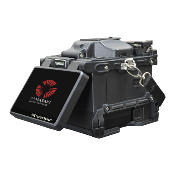
Within the scope of applicable law, our company, in any case, do not compensate for any special, incidental, indirect, secondary damage due to using this manual or the product, and also does not compensate for any loss of profits, data, goodwill or anticipated savings. Y91 Splicer Basics 2.1. Overview... -
Page 6: Keyboard
2.2. Keyboard Figure 2.2 Table 2.1 1. Power Light 2. Power 3. Up 4. Left 5. Down 6. Right 7. Menu / Exit 8. Enter 9. Heating light 10. Heat 11. Arc 12. Reset 13. Switch video 14. Auto splice... - Page 7 2.2.1. Keyboard Functions Whilst powered on, hold this button to power off • Whilst powered off, hold this button to power on • Under standby interface, press this button to discharge weak • In the menu screen, press this button to enter the next •...
- Page 8 Under standby interface, press this button to decrease the • LCD backlight In setup of CMOS sensor, press this button to decrease the • CMOS sensor backlight In motor adjustment, press this button to move the • corresponding motor down If permitted, press this button to move the cursor down •...
-
Page 9: Technical Parameters
2.3. Technical Parameters Table 2.3 Applicable Fiber SM, MM, DS, NZDS, EDFA, Others Cladding Diameter 80 – 150µm Coating Diameter 100 - 1000µm Typical Loss SM: ≤0.02dB; MM: ≤0.01dB; DS: ≤0.04dB; NZDS: ≤0.04dB Return Loss >60dB Cutting Length 5-16mm (Coating Layer Diameter: <250µm) 16mm (Coating Layer Diameter: 250~1000µm) Program 40 Groups... -
Page 10: Preparation Of The Fiber End Face
3.2. Fiber End-Face Preparation Prepare two optical fibers, as shown in Figure 3.2, and place one of the optical fibers inside a heat shrink protection sleeve for use later. This cannot be done after the splice is made! Figure 3.2 As shown in Figure 3.3, use the fiber strippers provided and place the fiber into the tooth of the clamp, Strip 30 to 40 mm of bare fiber. -
Page 11: Fiber Clamping
Open the small clamp, and carefully remove the fiber. Do not allow the fiber end-face to touch any other objects, to avoid any damage or contamination. Figure 3.4 13mm Note: Once the fiber is cleaved load it into the splicer immediately to avoid any contamination! 3.3. -
Page 12: Optical Fiber Fusion
Please operate carefully and don’t let the fiber end face touch any other objects. Then close the clamps to fix the optical fiber in place, which should be placed horizontally in the V-groove, without any upturn. If the clamping fails, you can remove the fiber carefully and repeat the operation above until the fiber clamping meets the requirements. -
Page 13: Heat-Shrinking
After examination of the end-face has taken place, the alignment motors will then adjust the position of the fiber, to make both sides of the fibers align. The last step will be the electrode’s discharge arc to fuse the fibers together. When this fusion is completed, the machine will give loss estimates, and perform a tension test if requested to do so. -
Page 14: Cooling
3.6. Cooling The heat-shrink tubing after being in the heater will be very hot and will need cooling. Place the cooling tray on the bolts behind the heater (see image below). Once heating is completed, remove the fused fiber from the heating furnace and load it into the cooling tray. -
Page 15: Main And Standby Interface
For the main menu interface : In the standby state, press to enter the interface of the main menu. In the main menu, press to exit the main menu to the standby interface. In the main menu, press the direction keys, and the corresponding direction on the next icon is selected. Press to enter the submenu. - Page 16 The status bar of the fusion splicer, showing the status of the fusion splicer and splicing process information The battery bar of the fusion splicer, shows the battery level. Display the fusion mode of the fusion splicer. Showing the current splice parameters. Showing the temperature of the heater.
-
Page 17: Shortcut
4.2 Shortcut The shortcut menu is for quick entry to some often-used menus. As shown below. 4.2.1. Fusion Starts Users can press or touch this menu to switch the fusion mode between Auto or Manual. - Page 18 4.2.2. Auto Arc Calibration See details on page 28 4.2.3 Manual Motor Adjust See details on page 26 4.2.4. Manual Fiber View Adjust This function is used to move the fiber image positions up/down/left/right. Press the key to enter the video interface.
-
Page 19: Fusion Mode
4.3. Fusion Mode The Fusion Mode menu is used to select and set the fiber splicing parameters and settings. 4.3.1. Fusion Mode The Fibre Type Menu is formed by different fiber type splicing parameters program sub-menus Each sub-menu is a group of splicing parameters, and the menu includes the number, file name, pattern and state. - Page 20 Auto parameters are derived from optimizations by the manufacturer and cannot be modified, this is the recommended mode to use for new users. The data of FAST and Normal can be modified except for the pre- discharge and post-discharge time. All the Normal parameters can be modified.
- Page 21 Arc Data Discharge current means the discharge arc current intensity. A high value of the current corresponds to a greater arc power, resulting in a higher temperature. The fiber is ablated more significantly. Press to increase/decrease the parameter value. Motor overlap The movement distance of a fiber during splice is called overlap.
- Page 22 Pause on Aligning It means fiber suspend the running at the end of the subsequent process of aligning. To continue splicing, press "SET" button or ▷ at the bottom of the screen. Press the key or touch this option, the parameter value will be switched between”...
- Page 23 Fiber Center View After Fusion When it is” ON”, the fiber is aligned and the fiber is centered during aligning process; when “OFF”, the fiber is not aligned, and it may not be centered. Press the key or touch this option, the parameter value will be switched between”...
-
Page 24: Settings
4.4. Settings The “Setting” menu is used to set the data including the operation mode, language, camera brightness, tension and auto shutdown, as explained below. Battery Save Mode When the option is turned on, if there is no operation within 10 minutes, the machine will automatically turn off to save battery power. - Page 25 Date and Time Press to enter the interface of Date and Time. Press to move the selection cursor, and then press to modify the selection value. Buzzer When this option is selected, when pressing the button or touching the screen, there will be a beep sound. When it is off, there will be no sound in such an operation.
-
Page 26: Maintenance
4.5. Maintenance The Maintenance menu consists of Quick Optimization, Auto Camera Focus Adjust, Auto Push Motor Test, Auto LED Calibration etc. Quick Optimization It is used for quick checking and automatic optimization of the fusion splicer. Load the fibers and press key to start. - Page 27 Manual Motor adjust Manual Motor adjust is used to check the performance of the motor and change the motor position. Press the key to enter the video interface. Press the key to switch the Left, Right, ZX and ZY motors. Press to move the motors UP/DOWN/BACK/FORWARD/FOCUSING to adjust the fiber position and images.
- Page 28 Fusion Records This option stores working parameters, fiber end face, the environment and date of each splice. The machine can store 10,000 groups of fusion records. can be pressed to enter the page of fusion record, and the page displays eight fusion records one each page, sequenced from top to bottom by the latest fusion splice.
-
Page 29: Arc
Export Records This option is used to export fusion records files saved in the machine. After the U disk is inserted into the USB port, choose this option and press the key to confirm “fusion records” export. The program begins to test the USB port and then finds the records. - Page 30 Manual Arc Calibration Manual Arc Calibration Manual Arc Calibration Manual Arc Calibration Cut and load fiber according to splice procedure, and then press the key to start The calibration program starts to run and test results are given. According to the test results, If the result value is red, it will give suggestions for the next step for parameter adjusting.
- Page 31 If the result value is green (shown in Figure 4.28), just do as the instructions, load a new fiber Completed after results shows “Calibration OK!”, New electrodes discharge instability and the necessary discharge to stabilize the arc is called electrodes stabilization.
-
Page 32: Heater
Current Arc Current Arc Count Count Current Arc Current Arc Count Count This option shows the Arc discharge times of current electrodes. Total Arc Count Total Arc Count Total Arc Count Total Arc Count This option shows the total Arc discharge times since the fusion splicer started working. Replace Electrodes Replace Electrodes Replace Electrodes... -
Page 33: Information
Heat Mode Users can choose different heat modes according to different heat shrink sleeves, it consists of Heat#25mm, Heat#40, Heat#50mm, Heat#60mm press key or touch this menu to change the heat mode. Heat Time Heat time can be set by users according to their specific heat shrink sleeves. Select this option “Heat Time”, and press the key to change the time. - Page 34 Below are instructions for how to clean the V-groove: 1. Place fiber with a known good end face into the V- groove to remove any pollution. 2. Use a cotton swab soaked with alcohol to clean the surface and bottom of the V-groove. The alcohol used should be naturally air-dried or wiped dry with a dry cotton swab.
-
Page 35: Replacing Electrodes
5.2 Replacing Electrodes Arcs produce high temperatures, which allows for the melting of the fibers, in turn producing silicon oxide vapour. Some of these deposits end up stuck on the electrodes, causing arc instability. Therefore, users are advised to replace the electrodes when 3000 arc counts have been reached or instability has become an issue. -
Page 36: Electrode Aging
5.3. Electrode Aging The electrodes arcs can become unstable when external environments (temperature, pressure, etc.) change drastically; Especially moving from low altitudes to high altitudes. When this occurs, users should perform the electrode aging process to stabilize the electrode. Note: Please follow instructions whilst operating in this mode, do not open the cover while electrodes aging. -
Page 37: Common Faults & Solutions
6. Common Faults and Solutions Table 6.1 Fault Reason Solution The fiber is broken, no fiber is Ensure both fiber end-faces loaded or the fiber is more “Please Check Fiber” are visible on the LCD Screen than 2mm away from prior to running the splice electrodes Press the reset key and reload... - Page 38 Under what circumstances did the problem arise? What is the current condition of the fusion splicer? Information regarding the display and the error tips etc. Contact manner Yamasaki Optical Technology: sales@yamasakiot.com Unit 3 15-16 Nicole Close Bayswater North VIC 3153 Australia...
Need help?
Do you have a question about the Y91 and is the answer not in the manual?
Questions and answers