
Summary of Contents for Ground Fault Systems DGF7
- Page 1 DGF7 Display reference manual Ground Fault Systems B.V. www.groundfaultsystems.com Rigtersbleek-Aalten 4B15 info@groundfaultsystems.com 7521 RB Enschede Tel: +31 53 4318628 The Netherlands CofC: 55400914...
-
Page 2: Table Of Contents
Table 1 - DGF7-3 dipswitch settings Table 2 - DGF7 Display settings versus current read-out Table 3 - Trip codes Figure 1 - Typical Field Connection using DGF7-3 with built-in core balance, remote reset and DGF7 Display. Figure 2 - Dimensions DGF7 Display DGF7 Display reference manual, rev. -
Page 3: General Description
The pushbuttons can also be used to test the segments of the LCD and to invoke a relay test on the DGF7-3. The display is connected to the DGF7-3 base unit using a single twisted pair of wires. No separate power supply is needed. -
Page 4: Functionality
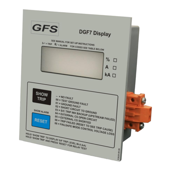
Relative format: as a percentage of the G/F Trip Level. The G/F Trip Level is set by means of dipswitches 1, 2 and 3 on the DGF7-3 base unit. It is the intention that the user checks the ‘%’ box on the DGF7 Display’s front panel with a marker. -
Page 5: Trip Code Display During Power Down Situations
The previous trip value is lost. 2.1.5 Reset function The DGF7 Display can be used to reset the DGF7-3 after a trip occurred. A reset will only be granted if the cause of the trip is not present anymore. -
Page 6: Lcd Test
E:04. At the moment only one error code is used: The DGF7 Display does not receive data via the datalink. This code may be seen for a few seconds when the base unit is powered down. DGF7 Display reference manual, rev. 1.2, June 11, 2024... -
Page 7: Parameter Setting
ARAMETER SETTING 3.1 Display Settings Five settable parameters stored in non-volatile memory enable the user to tailor the DGF7 Display to their needs. However, to discourage unauthorised manipulation, parameters can only be changed by going through the procedure outlined in section 3.2. -
Page 8: Connections And Precautions
Please consult the following checklist when applying the DGF7 Display. Place the DGF7 Display on the door or front panel of the clean dry enclosure that accommodates the DGF7-3 G/F Protection Unit it is connected to. The panel cut-out is a rectangle measuring 85 mm vertically, and 70 mm horizontally. -
Page 9: Technical Specifications
85 x 70 mm (H x W) Mounting bracket 2 pieces M5 x 16 plus rings and bracket supplied Weight (open) 0,16 kg Weight (packaged) 0,19 kg DGF7 Display reference manual, rev. 1.2, June 11, 2024 Ground Fault Systems B.V. -
Page 10: Applicable Standards
UL 1053 UL standard for Safety Ground-Fault Sensing and Relaying Equipment, Class 1. CSA C22.2 NO. 144-M1991 CSA standard for Ground Fault Circuit Interrupters. File E203514 CE mark – Declaration of Conformity DGF7 Display reference manual, rev. 1.2, June 11, 2024 Ground Fault Systems B.V. -
Page 11: Tables And Figures
Trip Inhibit Operating Mode L L ♦ Continuous Non-Failsafe operation Continuous Failsafe operation Pulsed Non-Failsafe operation Pulsed Failsafe operation ♦ Factory settings Back to G/F Trip Level display. DGF7 Display reference manual, rev. 1.2, June 11, 2024 Ground Fault Systems B.V. - Page 12 Table 2 - DGF7 Display settings versus current read-out Values are primary currents. 0 (a) 0 (b) DGF7-3 Internal/ Interposing External External External Interposing setting external 5000:5 1000:1 2000:1 10.000:1 500:5 500:1 0,030 A 0,030 A 0,030 kA 0,060 A...
- Page 13 DGF7-3 will now show the original trip’s flashing code. FAILSAFE LOSS OF CONTROL VOLTAGE The DGF7-3 base unit is used in one of the failsafe trip relay modes, and it lost Control Voltage while not being tripped. Back to Trip code display.
- Page 14 Figure 1 - Typical Field Connection using DGF7-3 with built-in core balance, remote reset and DGF7 Display. DGF7 Display reference manual, rev. 1.2, June 11, 2024 Ground Fault Systems B.V.
- Page 15 Figure 2 - Dimensions DGF7 Display DGF7 Display reference manual, rev. 1.2, June 11, 2024 Ground Fault Systems B.V.
Need help?
Do you have a question about the DGF7 and is the answer not in the manual?
Questions and answers