
Summary of Contents for Brightwell Brightlogic 10 Pump Controller
- Page 1 Brightlogic 10 Pump Controller Installation Guide Installation and Setup Brightwell.co.uk Revision 1.1 02/2023 B995...
-
Page 2: Table Of Contents
Safety InfoRmatIon CONTENTS SAFETY INFORMATION ---------------------------------------------------------------------------------------------------------3 Safety PReCaUtIonS ---------------------------------------------------------------------------------------------------------------------------------------------------- 4 ----------------------------------------------------------------------------------------------------------------------------------------------------------------------- 5 oPeRatIon UNIT LAYOUT -------------------------------------------------------------------------------------------------------------------------7 UnIt LayoUt - mICRoBoaRD ------------------------------------------------------------------------------------------------------------------------------------------ 8 ------------------------------------------------------------------------------------------------------------------------------------------ 9 UnIt LayoUt - ReLay BoaRD WIRING ---------------------------------------------------------------------------------------------------------------------------------10 InStaLLatIon - WIRInG 1 ------------------------------------------------------------------------------------------------------------------------------------------------11 ------------------------------------------------------------------------------------------------------------------------------------------------12 InStaLLatIon - WIRInG 2 InStaLLatIon - Hot &... -
Page 3: Safety Information
Safety InfoRmatIon Safety InfoRmatIon Safety PReCaUtIonS oPeRatIon Important Safety Instructions 10 Pump Controller units are able to control the external operation of alternative equipment rather than Brightlogic pumps. However, it is possible to utilize both type of pumps simultaneously with Please read the following precautions carefully before using this equipment. -
Page 4: Unit Layout
Safety InfoRmatIon UnIt LayoUt oPeRatIon Silencing the alarm Press the ‘Snooze‘ button on the front panel momentarily, this silences the buzzer for the set period selected. After the snooze period has elapsed, the alarm will resume again until the sensors no longer indicate an alarm condition. However, the active channel indicators will stay on throughout the entire alarm period until the sensors no longer indicate an alarm condition. -
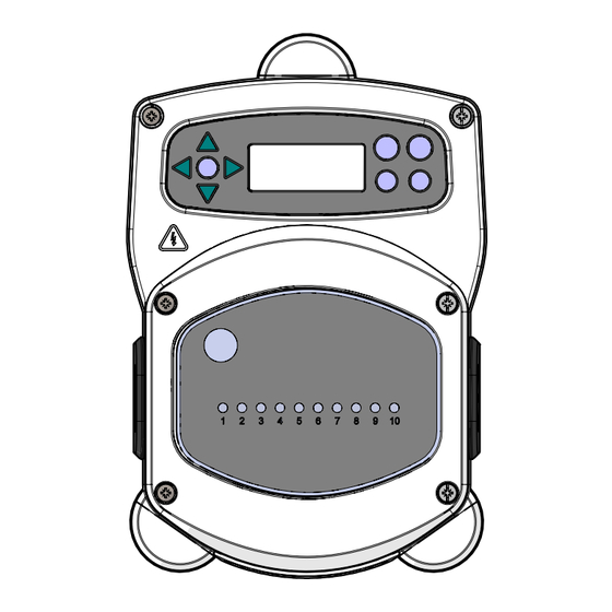
Page 5: Unit Layout - Microboard
UnIt LayoUt UnIt LayoUt UnIt LayoUt - mICRoBoaRD UnIt LayoUt - ReLay BoaRD Pump selector Alarm input from Alarm ‘Snooze’ RS485 connection OUT switch controller board time (off - 60mins) for Add-on pumps 24V Alarm Output Wireless USB Module LCD Display RS485 Connection IN from controller board. -
Page 6: Wiring
WIRInG WIRInG InStaLLatIon - WIRInG 1 In most cases, the interface board or solenoids in the host machine will have a common (i.e their negative terminals are all linked by a common wire). the switches S1 & S2 can be left switched to common (up position), and the single (common) wire taken to the B rail. -
Page 7: Installation - Hot & Cold Mode
WIRInG WIRInG InStaLLatIon - WIRInG 2 InStaLLatIon - Hot & CoLD moDe In some cases, the interface board or solenoids in the hose machine are not common. For If you are wiring for Hot & Cold mode, please note that the number of trigger inputs from the example: the softener solenoid on some machines is not linked via a common wire to the other machine will be changed. -
Page 8: Programming
WIRInG PRoGRammInG InStaLLatIon - WIRInG 3 24 V external alarm module Relay Alarm volt free Input (0V - 230V AC DC 1A) Relay Alarm output Wiring to external pump 1 Wiring to external pump 2 Wiring to external Wiring to external pump 8 pump 3 Wiring to external... -
Page 9: Programming - Controls
Use the UP and DOWN keys to scroll through the language options. Press the FWD/ACCEPT key to select the displayed 00000 ENTER CODE TO ENTER CODE TO CHANGE LANGUAGE CHANGE LANGUAGE BRIGHTWELL ---- 1--- PRoGRammInG - Key to InStRUCtIonS ENTER CODE TO CHANGE LANGUAGE ENGLISH... -
Page 10: Flow Diagram - Instructions
PRoGRammInG PRoGRammInG fLoW DIaGRam - InStRUCtIonS fLoW DIaGRam - InStRUCtIonS CyCLe tImeoUt Set ReSet to 60 mInS featURe off PRoGRam 01 Set ReSet to Set InPUt 02 InPUt 10 PRoGRam 01 PRoGRam 01 PRoGRam 01 PRoGRam 01 Set InPUt 01 Set InoUt 01 Set InPUt 01 Set InPUt 01... -
Page 11: Formula Select - Safety Precautions
PRoGRammInG PRoGRammInG foRmULa SeLeCt - Safety PReCaUtIonS foRmULa SeLeCt - InStaLLatIon fit the module to a suitable surface, in an accessible area, using the self-adhesive Velcro Important Safety Instructions provided. Before fitting, please ensure that the power to the unit has been isolated. Please read the following precautions carefully before using this equipment. -
Page 12: Low Level Alarm
PRoGRammInG PRoGRammInG LoW LeVeL aLaRm aDD on PUmPS & SPeCIfICatIon Revision 1.1 Revision 1.1 02/2023 02/2023 B995 B995...
Need help?
Do you have a question about the Brightlogic 10 Pump Controller and is the answer not in the manual?
Questions and answers