Table of Contents
Advertisement
Available languages
Available languages
Quick Links
ALLEN + ROTH and logo design are trademarks
or registered trademarks of LF, LLC.
All Rights Reserved.
Serial Number ___________
Purchase Date ___________
Questions, problems, missing parts? Before returning to your retailer, call our customer
service department at 866-439-9800, 8 a.m. - 8 p.m., EST, Monday - Sunday. You could
also contact us at ascs@lowes.com .
SG24060
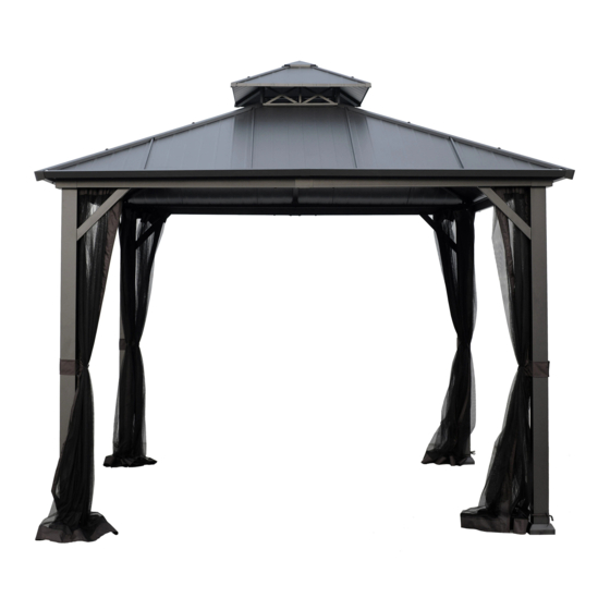
HARD TOP GAZEBO
ATTACH YOUR RECEIPT HERE
1
ITEM #5106734
MODEL #TPGAZ2246
Español p. 28
Advertisement
Chapters
Table of Contents

Related Manuals for LF ALLEN+ROTH TPGAZ2246

Summary of Contents for LF ALLEN+ROTH TPGAZ2246
- Page 1 ITEM #5106734 HARD TOP GAZEBO MODEL #TPGAZ2246 ALLEN + ROTH and logo design are trademarks or registered trademarks of LF, LLC. Español p. 28 All Rights Reserved. ATTACH YOUR RECEIPT HERE Serial Number ___________ Purchase Date ___________ Questions, problems, missing parts? Before returning to your retailer, call our customer service department at 866-439-9800, 8 a.m.
-
Page 2: Table Of Contents
TABLE OF CONTENTS Package Contents ........................3 Hardware Contents ........................5 Safety Information ........................6 Preparation ..........................6 Installation Instructions ........................7 Care and Maintenance ........................ 26 Warranty ............................26 Replacement Parts List ....................... 27... -
Page 3: Package Contents
PACKAGE CONTENTS PART DESCRIPTION QUANTITY PART DESCRIPTION QUANTITY Post Mosquito Net Tube Base Cover Connector Tube Base Plate Long Roof Support Left Lintel Short Roof Support Right Lintel Main Roof Support Main Roof Support Protective Corner Strut Left Brace Right Brace Strut Lintel Connector Main Roof Support... - Page 4 PACKAGE CONTENTS PART DESCRIPTION DESCRIPTION PART DESCRIPTION QUANTITY PART DESCRIPTION QUANTITY Edge Banding Small Roof Support Mosquito Net Vented Roof Frame Small Top Cover Vented Roof Net Central Device Vented Roof Panel Hook Big Top Panel Cover Big Top Panel Small Top Ridge Big Top Panel Big Top Ridge...
-
Page 5: Hardware Contents
HARDWARE CONTENTS (NOT TO SCALE) Washer Qty. 280 + 10 Extra M6 × 15 mm Bolt Qty. 220 + 8 Extra M6 × 25 mm Bolt M6 × 20 mm Bolt Qty. 8 + 1 Extra M6 × 35 mm Bolt Qty. -
Page 6: Safety Information
SAFETY INFORMATION Please read and understand this entire manual before attempting to assemble or install the product. WARNING • Maximum load for the roof hook: 50 lbs. • WARNING: KEEP ALL FLAME AND HEAT SOURCES AWAY FROM THIS TENT FABRIC. This tent meets the CPAI-84 flammability requirements. -
Page 7: Installation Instructions
INSTALLATION INSTRUCTIONS Hardware Used 1. Insert the Base Cover (B) into the Post (A), and then connect the Base Plate (C) to the Post (A) by Bolt (AA) and Flat Washer (EE). Tighten together with the wrench (NN). Place Bolt Cover (GG) on the bolt (AA). - Page 8 INSTALLATION INSTRUCTIONS Hardware Used Note: The holes on the Cover (G) are facing inward 2.1 Insert the Lintel connector (F) into the Right Lintel (D2), connect them first to the holes with bolts (AA) and washers (EE) as shown in the picture, then insert the Cover (G) and Left Lintel (D1) to the Right Lintel (D2) at the same time, and fix them with bolts (AA) and washers (EE) as shown in the picture.
- Page 9 INSTALLATION INSTRUCTIONS Hardware Used 3.1 Connect the Mosquito Net Tube Connector (G2) to the Cover (G) by sliding it into the Bolt (JJ), washers (EE), and the Plastic gasket (PP) . 3.2 Slide one end of the mosquito net tube (G1) into the Connector tube (G2), connect the other end to the lintels (D1/D2) with bolt (JJ), washers (EE), and Plastic gasket (PP).
- Page 10 INSTALLATION INSTRUCTIONS Hardware Used 4. Connect the assembled Lintels (D1/D2) to the Post (A) with bolts (II) .
- Page 11 INSTALLATION INSTRUCTIONS Hardware Used 5.1 Connect Lintel (D1/D2) to Post (A), and fix them with Bolt (II). 5.2.Connect Protective Corner (E) to Lintel (D1/D2), and fix them with Bolts (AA), Washer (EE) and Bolt Cover (GG).
- Page 12 INSTALLATION INSTRUCTIONS Hardware Used 6. Connect one end of the Braces (E1/E2) with bolts (AA) and washers (EE) to the Post (A), connect the other end to the Lintels (D1/D2). Finally put on the Bolt Cover (GG) over all bolts.
- Page 13 INSTALLATION INSTRUCTIONS Hardware Used 7.1 Connect the Top Support Connector (F1) to the Long Roof Support (H) with Bolts (AA), Washer (EE) and Bolt Cover (GG). 7.2 Connect one end of the Long Roof Support (H) to the Center Frame (M), connect the other end to the Post (A) with Bolts (AA), Washer (EE) and Bolt Cover (GG).
- Page 14 INSTALLATION INSTRUCTIONS Hardware Used 8. Connect one end of the Short Roof Support (I) to the Center Frame (M), connect the other end of the Short Roof Support (I) to the Connector (F2) with the Bolts (AA), Washer (EE) and Bolt Cover (GG).
- Page 15 INSTALLATION INSTRUCTIONS Hardware Used 9.1 Screw the Hook (O3) onto the Center Device (O2) . 9.2 Connect the Small Roof Support (N1) to the Center Device (O2) with the Bolts (DD), Washer (EE) , Nut (HH) and Cap (OO).
- Page 16 INSTALLATION INSTRUCTIONS Hardware Used 10. Connect the assembled vented roof to the Center Frame (M) with Bolts (AA), Washer (EE) and Bolt Cover (GG).
- Page 17 INSTALLATION INSTRUCTIONS Hardware Used 11. Connect the Vented Roof Panel (T) to the Small Roof Support (N1) by Bolt (AA) and Flat Washer (EE). Tighten together with the wrench (NN). Place Bolt Cover (GG) on the Bolt (AA).
- Page 18 INSTALLATION INSTRUCTIONS Hardware Used 12.1 Connect the Small Top Ridge (Q1) to the Small Roof Support (N1) with the Bolts (BB), Plastic Washer (KK), and Bolt Cover (GG). 12.2 Snap the Small Top Cover (O1) onto the Center Device (O2) with the Bolt Washer (LL).
- Page 19 INSTALLATION INSTRUCTIONS Hardware Used 13. Connect Vented Roof Frame (N2) to the Small Roof Support (N1) with Bolts (CC), Washer (EE), and Bolt Cover (GG). Nut (HH)
- Page 20 INSTALLATION INSTRUCTIONS Hardware Used 14.1 Attach the Main Roof Supports (L1 and L2) to the Roof Support (H and I) with Bolts (AA), Washer (EE) and Bolt Cover (GG). 14.2 Attach the Main Roof Supports(J1 and J2) to the Roof Support (H and I) with Bolts (AA), Washer (EE) and Bolt Cover (GG).
- Page 21 INSTALLATION INSTRUCTIONS Hardware Used 15. Connect the Struts (K1/K2) to the Long Roof Support (H) and the Short Roof Support (I) with the bolt (AA) and washer (EE), snap on the Bolt Cover (GG).
- Page 22 INSTALLATION INSTRUCTIONS Hardware Used the connected shape of steel top panel K1 K2 16. Connect the Big Top Panels (U1/U2/U3/U4/U5) as the order shown in the figure. Fix it with the bolts (AA) and washers (EE) when connecting the large top plate (U1/U5). When connecting the large top plate (U2/U3/U4), connect the pressure plate (V) to the Strut (K1/K2) with the bolts (FF) and washers (EE) at the same time.
- Page 23 INSTALLATION INSTRUCTIONS Hardware Used 17.1 Connect the Edge Banding (R2/R3) to the Struts (K1/K2) with bolts (AA) and washers (EE). 17.2 Connect the Cover (P) to the Short Roof Support (I) with Bolts (AA), Washer (EE) and Bolt Cover (GG). 17.3.
- Page 24 INSTALLATION INSTRUCTIONS Hardware Used 18. Connect the Big Top Ridge (Q2) to the Long Roof Support (H) with the Bolts (CC), Plastic Washer (KK) and Bolt Cover (GG).
- Page 25 INSTALLATION INSTRUCTIONS Hardware Used 19.1 Install the vented roof net (S2) to the vented roof Support (N1) . 19.2 Hang the Mosquito Net (S1) onto the Sliding Tube (G1) by (MM). Plastic Ring Connectors 19.3 Adjust position of gazebo and anchor posts to the ground by inserting the Stakes (RR) into each hole in each Base Plate.
-
Page 26: Care And Maintenance
CARE AND MAINTENANCE • For cleaning, use a mild detergent solution, rinse with water, and allow to air dry. Do not use acetone, abrasive, or other special detergents as they would be harmful to the product’s finish. • Due to the nature of steel, surface oxidation (rusting) will occur if this protective coating is scratched. This is a natural process. -
Page 27: Replacement Parts List
REPLACEMENT PARTS LIST For replacement parts, call our customer service department at 866-439-9800, 8 a.m. - 8 p.m., EST, Monday - Sunday. You could also contact us at ascs@lowes.com. PART DESCRIPTION PART # PART DESCRIPTION PART # Screw Nut M6 x 15 mm Bolt M6 x 15 mm Bolt M6 x 25 mm Bolt M6 x 40 mm Bolt... - Page 28 ARTÍCULO #5106734 ALLEN + ROTH y el diseño del logotipo son marcas comerciales o marcas registradas de MODELO #TPGAZ2246 LF, LLC. Todos los derechos reservados. ADJUNTE SU RECIBO AQUÍ Número de serie ___________ Fecha de compra ___________ ¿Preguntas, problemas, piezas faltantes? Antes de volver a la tienda, llame a nuestro Departamento de Servicio al Cliente al 866-439-9800, de lunes a domingo de 8 a.m.
- Page 29 ÍNDICE Contenido del paquete ........
-
Page 30: Contenido Del Paquete
CONTENIDO DEL PAQUETE PIEZA DESCRIPCIÓN CANTIDAD PIEZA DESCRIPCIÓN CANTIDAD Poste Tubo de mosquitero Cubierta de la base Tubo conector Placa de base Soporte de techo largo Dintel izquierdo Soporte de techo corto Soporte de techo principal Dintel derecho Soporte de techo principal Esquina protectora Tirante izquierdo Puntal... - Page 31 CONTENIDO DEL PAQUETE PART DESCRIPTION DESCRIPTION PIEZA DESCRIPCIÓN CANTIDAD PIEZA DESCRIPCIÓN CANTIDAD Ribetes de borde Soporte de techo pequeño Estructura del techo ventilado Mosquitero Cubierta superior pequeña Red de techo ventilada Dispositivo central Panel de techo ventilado Gancho Panel superior grande Cubierta Panel superior grande Cumbrera superior pequeña...
-
Page 32: Aditamentos
ADITAMENTOS (NO SE MUESTRAN A ESCALA) Arandela cant. 280 +10 adicionales Perno M6 x 15 mm cant. 220 Perno M6 x 20 mm Perno M6 x 25 mm + 8 adicionales cant. 24 + 2 adicionales cant. 8 + 1 adicional Perno M6 x 35 mm cant. -
Page 33: Información De Seguridad
INFORMACIÓN DE SEGURIDAD Lea y comprenda completamente este manual antes de intentar ensamblar o instalar el producto. ADVERTENCIA • Carga máxima para el gancho del techo: 22,67 kg • ADVERTENCIA: MANTENGA LA TELA DE LA TIENDA ALEJADA DE LAS LLAMAS Y LAS FUENTES DE CALOR. -
Page 34: Instrucciones De Instalación
INSTRUCCIONES DE INSTALACIÓN Aditamentos utilizados 1. Inserte la cubierta para base (B) en el poste (A) y luego conecte la placa base (C) al poste (A) con un perno (AA) y una arandela plana (EE). Apriete con la llave inglesa (NN). Coloque la cubierta para perno (GG) en el perno (AA). - Page 35 INSTRUCCIONES DE INSTALACIÓN Aditamentos utilizados Note: The holes on the Cover (G) are facing inward 2.1 Inserte el conector del dintel (F) en el dintel derecho (D2), conéctelos primero a los orificios con pernos (AA) y arandelas (EE), como se muestra en la imagen, luego inserte la cubierta (G) y el dintel izquierdo (D1) al dintel derecho (D2) al mismo tiempo y fíjelos con pernos (AA) y arandelas (EE), como se muestra en la imagen.
- Page 36 INSTRUCCIONES DE INSTALACIÓN Aditamentos utilizados 3.1 Conecte el conector del Tubo conector (G2) a la cubierta (G) deslizándolo en el perno (JJ), las arandelas (EE) y el empaque de plástico (PP). 3.2 Deslice un extremo del tubo del mosquitero (G1) en el conector del tubo del mosquitero (G2), conecte el otro extremo a los dinteles (D1/D2) con un perno (JJ), arandelas (EE) y un empaque de plástico (PP).
- Page 37 INSTRUCCIONES DE INSTALACIÓN Aditamentos utilizados 4. Conecte los dinteles ensamblados (D1/D2) al poste (A) con pernos (II).
- Page 38 INSTRUCCIONES DE INSTALACIÓN Aditamentos utilizados 5.1 Conecte el dintel (D1/D2) al poste (A) y fíjelos con un perno (II). 5.2 Conecte la esquina protectora (E) al dintel (D1/D2) y fíjelos con pernos (AA), una arandela (EE) y una cubierta para pernos (GG).
- Page 39 INSTRUCCIONES DE INSTALACIÓN Aditamentos utilizados 6. Conecte un extremo de los tirantes (E1/E2) con pernos (AA) y arandelas (EE) al poste (A), conecte el otro extremo a los dinteles (D1/D2). Finalmente, coloque cubiertas para pernos (GG) sobre todos los pernos.
- Page 40 INSTRUCCIONES DE INSTALACIÓN Aditamentos utilizados 7.1 Conecte el conector de soporte superior (F1) al soporte de techo largo (H) con pernos (AA), una arandela (EE) y una cubierta para perno (GG). 7.2 Conecte un extremo del soporte de techo largo (H) a la estructura central (M), conecte el otro extremo al poste (A) con pernos (AA), una arandela (EE) y una cubierta para perno (GG).
- Page 41 INSTRUCCIONES DE INSTALACIÓN Aditamentos utilizados 8. Conecte un extremo del soporte de techo corto (I) a la estructura central (M), conecte el otro extremo del soporte de techo corto (I) al conector (F2) con pernos (AA), una arandela (EE) y una cubierta para perno (GG).
- Page 42 INSTRUCCIONES DE INSTALACIÓN Aditamentos utilizados 9.1 Atornille el gancho (O3) en el dispositivo central (O2). 9.2 Conecte el soporte de techo pequeño (N1) al dispositivo central (O2) con pernos (DD), una arandela (EE), una tuerca (HH) y una tapa (OO).
- Page 43 INSTRUCCIONES DE INSTALACIÓN Aditamentos utilizados 10. Conecte el techo ventilado ensamblado a la estructura central (M) con pernos (AA), una arandela (EE) y una cubierta para perno (GG).
- Page 44 INSTRUCCIONES DE INSTALACIÓN Aditamentos utilizados 11. Conecte el panel de techo ventilado (T) al soporte de techo pequeño (N1) con un perno (AA) y una arandela plana (EE). Apriete con la llave inglesa (NN). Coloque la cubierta para perno (GG) en el perno (AA).
- Page 45 INSTRUCCIONES DE INSTALACIÓN Aditamentos utilizados 12.1 Conecte la cumbrera superior pequeña (Q1) al soporte de techo pequeño (N1) con pernos (BB), una arandela de plástico (KK) y una cubierta para perno (GG). 12.2 Encaje la cubierta superior pequeña (O1) en el dispositivo central (O2) con un perno (LL).
- Page 46 INSTRUCCIONES DE INSTALACIÓN Aditamentos utilizados 13. Conecte la estructura del techo ventilado (N2) al soporte del techo pequeño (N1) con pernos (CC), una arandela (EE), una tuerca (HH) y una cubierta para perno (GG).
- Page 47 INSTRUCCIONES DE INSTALACIÓN Aditamentos utilizados 14.1 Fije los soportes principales del techo (L1 y L2) al soporte de techo (H e I) con pernos (AA), una arandela (EE) y una cubierta para pernos (GG). 14.2 Fije los soportes principales del techo (J1 y J2) al soporte de techo (H e I) con pernos (AA), una arandela (EE) y una cubierta para pernos (GG).
- Page 48 INSTRUCCIONES DE INSTALACIÓN Aditamentos utilizados 15. Conecte los puntales (K1/K2) al soporte de techo largo (H) y al soporte de techo corto (I) con un perno (AA) y una arandela (EE), coloque a presión la cubierta para perno (GG).
- Page 49 INSTRUCCIONES DE INSTALACIÓN Aditamentos utilizados the connected shape of steel top panel K1 K2 16. Conecte los paneles superiores grandes (U1/U2/U3/U4/U5) en el orden que se muestra en la figura. Fíjelo con pernos (AA) y arandelas (EE) cuando conecte la placa superior grande (U1/U5).
- Page 50 INSTRUCCIONES DE INSTALACIÓN Aditamentos utilizados 17.1 Conecte el amarre (R2/R3) a los puntales (K1/K2) con pernos (AA) y arandelas (EE). 17.2 Conecte la cubierta (P) al soporte de techo corto (I) con pernos (AA), arandelas (EE) y cubierta para pernos (GG). 17.3 Conecte la cumbrera superior grande (Q2) al soporte de techo largo (H) con pernos (AA), una Arandela de plástico (KK) y una cubierta para perno (GG).
- Page 51 INSTRUCCIONES DE INSTALACIÓN Aditamentos utilizados 18. Conecte la pieza en L (R1) a la estructura central (M) con un perno (AA) y una arandela (EE). Encaje la cubierta para perno (GG).
- Page 52 INSTRUCCIONES DE INSTALACIÓN Aditamentos utilizados 19.1 Instale la red del techo ventilado (S2) en el soporte del techo ventilado (N1). 19.2 Cuelgue el mosquitero (S1) en el tubo corredizo (G1) con conectores de anillo de plástico (MM). 19.3. Ajuste la posición del gazebo y sujete los postes al suelo insertando las estacas (RR) en cada orificio de cada placa base.
-
Page 53: Cuidado Y Mantenimiento
CUIDADO Y MANTENIMIENTO • Para limpiar, use una solución de detergente suave, enjuague con agua y deje secar al aire. No use acetona, productos abrasivos ni otros detergentes especiales porque dañarían el acabado del producto. • Debido a la naturaleza del acero, puede producirse oxidación superficial si este recubrimiento protector se raya. GARANTÍA 2 AÑOS DE GARANTÍA PARA LA ESTRUCTURA, 1 AÑO DE GARANTÍA PARA LA TELA. -
Page 54: Lista De Piezas De Repuesto
LISTA DE PIEZAS DE REPUESTO Para obtener piezas de repuesto, llame a nuestro Departamento de Servicio al Cliente al , de lunes a domingo. También puede ponerse en contacto con nosotros ascs@lowes.com PIEZA DESCRIPCIÓN PIEZA # PIEZA DESCRIPCIÓN PIEZA # Tuerca para tornillo Perno M6 x 15 mm Perno M6 x 15 mm...
Need help?
Do you have a question about the ALLEN+ROTH TPGAZ2246 and is the answer not in the manual?
Questions and answers