Advertisement
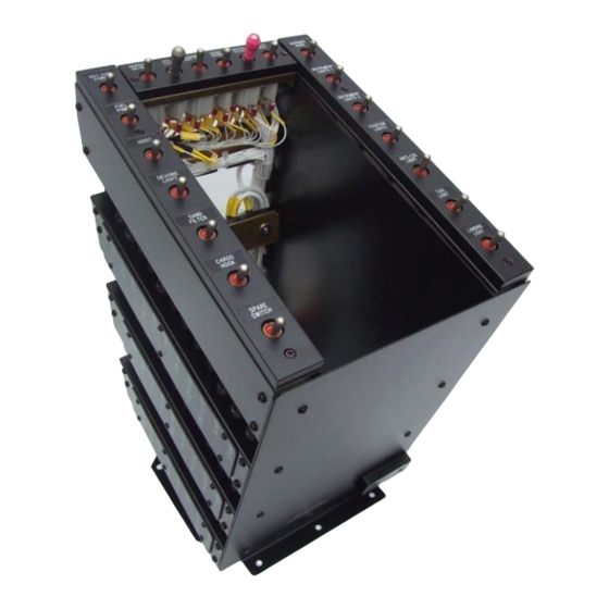
P132 Console
Installation Instructions
GA107-6
INSTALLATION INSTRUCTION
REV 1.00 November 15, 2022
Anodyne Electronics Manufacturing Corp.
966 Crowley Ave Unit #100
Kelowna, BC, Canada.
V1Y 0L1
Telephone: +1-250-763-1088
Toll Free: +1-888-763-1088
Website: www.aem-corp.com
© 2022 Anodyne Electronics Manufacturing Corp. (AEM),
All Rights Reserved
CONFIDENTIAL AND PROPRIETARY TO ANODYNE ELECTRONICS MANUFACTURING CORP.
Page 1 of 18
Advertisement
Table of Contents

Related Manuals for AEM P132

Summary of Contents for AEM P132
- Page 1 Anodyne Electronics Manufacturing Corp. 966 Crowley Ave Unit #100 Kelowna, BC, Canada. V1Y 0L1 Telephone: +1-250-763-1088 Toll Free: +1-888-763-1088 Website: www.aem-corp.com © 2022 Anodyne Electronics Manufacturing Corp. (AEM), All Rights Reserved CONFIDENTIAL AND PROPRIETARY TO ANODYNE ELECTRONICS MANUFACTURING CORP. Page 1 of 18...
-
Page 2: Introduction And General Information
1.40 The P132 console is both taller and wider than the Airbus Helicopters original console, which may limit cyclic travel under certain conditions. Modifications to the flight controls are required to correct this and these are described in section 4.00. - Page 3 P132 Console GA107-6 Installation Instructions 1.150 The console labels for the circuit breakers are normally provided with the console kit. However, the installer may use any labeling method that provides clear indication of the circuit breaker's function. 1.160 This installation is a major rewiring of the electrical system for the aircraft. You should anticipate all of the possible failure modes in order to prevent them.
- Page 4 The Master Cutoff and Hydraulic Test must have locking toggles. For all other switches installed, the toggle may be either non-locking or locking, at the installer’s discretion, regardless of how the console was supplied from AEM. 1.260 Switch toggles may be color-coded to help identify the switch. RED color coding is REQUIRED for the Master Cutoff switch, and may not be used elsewhere.
- Page 5 If all of the breakers are removed from this panel, then the installer may, at their discretion, cover the empty panel with cover plate G12899. The P132 Console will limit cyclic travel toward the console if the Pilot’s and/or Copilot’s leg is 3.40 trapped between the console and the cyclic.
-
Page 6: New Style
These angle supports are used as the forward support for the P132 Console, and as guidelines for removing the angled aluminum box. NEW STYLE... - Page 7 P132 Console GA107-6 Installation Instructions REMOVE RIVETS BEFORE AFTER REMOVAL REMOVAL CUT LINE VIEW FROM ABOVE Fig. 3 4.13 Remove and discard the 4 nutplates from the aft side of the supports. Fig 4 4.14 Remove the angled box from the instrument panel support using figures 1 through 4 as a guide.
- Page 8 Fig. 5 4.49 For aircraft that are post-MOD 350A07-4280 (Multi-Bloc Console), refer to drawing G13132 for structural modifications required to install the P132 Console. 4.50 Route all new wires along existing bundles. See FAA AC43.13-1B, chapter 11 for acceptable methods for routing, lacing and securing bundles.
- Page 9 P132 Console GA107-6 Installation Instructions 4.70 Wire Connectors P1, P2, and the optional P3, in accordance with all pages of G12132 and the following instructions. Organize and label airframe the airframe wires assigned to the new connectors that will mate with the console connectors. Group the wires into separate bundles for each connector.
- Page 10 This STC requires compliance with the SB. However, this STC allows for the substitution of the AEM Hooking Lock (Collective Fitting) in place of the part number listed in the SB at the installer’s discretion. For p/n 350A27-3155-22 use G12733. For p/n 350A27-3155-21 or 350A08-2363-20 use G12957.
-
Page 11: Function Test Procedure
P132 Console GA107-6 Installation Instructions 5.00 FUNCTION TEST PROCEDURE 5.10 Test all electrical systems and equipment on the aircraft, not just what is listed in this section. Refer to the aircraft flight manual and its supplements for operational information, as well as the documents used for installation. - Page 12 P132 Console GA107-6 Installation Instructions 5.70 Function Test Procedure 1 (used for most devices) 5.71 Check that the device is truly powered off. 5.72 Close the breaker for that device by pressing in the plunger. 5.73 Check that the device is powered on if the breaker powers the device directly, or that the device is still powered off if the power needs to pass through a switch.
- Page 13 P132 Console GA107-6 Installation Instructions FUNCTION TEST PROCEDURE Use the column that matches the aircraft model to Model Model perform the correct functional test B, BA,B1, Note: *B2 refers to B2 models Post–Mod 350A07-3273 B2, C, D, Circuit Procedure Initials...
- Page 14 P132 Console GA107-6 Installation Instructions Circuit Procedure Initials Initials Avionics Master Function Test Procedure 1. Oil Cooling Fan Open switch at 30E; Fan OFF. Jumper terminals at 30E; Fan On Fuel Quantity Function Test Procedure 1. Check that fuel quantity reading...
- Page 15 P132 Console GA107-6 Installation Instructions Circuit Procedure Initials Initials GOV (FADEC) Function Test Procedure 1. (B3 only) All Optional Circuits Function Test Procedure 1 and/or other tests as appropriate. Crank Function Test Procedure 1. Switch on runs engine starter motor without igniters firing.
- Page 16 P132 Console GA107-6 Installation Instructions REMARKS (Customization, variations, model specific variations, etc) REMARKS SECTION COMPLETED BY: ____________ ___________ Name, Title, A&P No. Date Rev. 1.00 15 November 2022 Page 16 of 18 CONFIDENTIAL AND PROPRIETARY TO ANODYNE ELECTRONICS MANUFACTURING CORP.
-
Page 17: Return To Service
Update the aircraft equipment list. 6.40 Install the GA107-2-P132 FLIGHT MANUAL SUPPLEMENT in the appropriate place in the aircraft flight manual. Be sure to fill in the blanks on the cover page to show the aircraft registration number and serial number. -
Page 18: Copyright Statement
© 2022 Anodyne Electronics Manufacturing Corp. (AEM), All Rights Reserved This publication is the property of AEM and is protected by Canadian copyright laws. No part of this document may be reproduced or transmitted in any form or by any means including electronic, mechanical, photocopying, recording, or otherwise, without the prior written permission of AEM.
Need help?
Do you have a question about the P132 and is the answer not in the manual?
Questions and answers