ASROCK 870 EXTREME3 User Manual
Hide thumbs
Also See for 870 EXTREME3:
- Installation manual (223 pages) ,
- Specifications (8 pages) ,
- Quick installation manual (247 pages)

Related Manuals for ASROCK 870 EXTREME3


Summary of Contents for ASROCK 870 EXTREME3
-
Page 1: User Manual
870 Extreme3 User Manual Version 2.0 Published March 2011 Copyright©2011 ASRock INC. All rights reserved. 1 1 1 1 1... - Page 2 (including damages for loss of profits, loss of business, loss of data, interruption of business and the like), even if ASRock has been advised of the possibility of such damages arising from any defect or error in the manual or product.
-
Page 3: Table Of Contents
2.10 Dr. Debug .................. 30 2.11 Serial ATA3 (SATA3) Hard Disks Installation ......34 2.12 Hot Plug and Hot Swap Functions for SATA3 HDDs ....34 2.13 SATA3 HDD Hot Plug Feature and Operation Guide ....35 2.14 Driver Installation Guide ............37 2.15 Installing Windows... - Page 4 3 . 3 . 3 . 3 . 3 . UEFI S UEFI S UEFI S UEFI SETUP UTILITY ETUP UTILITY ETUP UTILITY ETUP UTILITY ..........................................41 UEFI S ETUP UTILITY ............ Introduction ................41 3.1.1 UEFI Menu Bar ..............41 3.1.2 Navigation Keys .............
-
Page 5: Package Contents
ASRock’s commitment to quality and endurance. In this manual, chapter 1 and 2 contain introduction of the motherboard and step-by-step guide to the hardware installation. Chapter 3 and 4 contain the configuration guide to BIOS setup and information of the Support CD. -
Page 6: Specifications
- Support for Socket AM3+ processors - Support for Socket AM3 processors: AMD Phenom II X6 / X4 / X3 / X2 (except 920 / 940) / Athlon II X4 / X3 / X2 / Sempron processors - Supports 8-Core CPU... - Page 7 - 1 x RJ-45 LAN Port with LED (ACT/LINK LED and SPEED LED) - 1 x IEEE 1394 Port - 1 x Clear CMOS Switch with LED - HD Audio Jack: Side Speaker/Rear Speaker/Central/Bass/ Line in/Front Speaker/Microphone (see CAUTION 6) SATA3 - 5 x SATA3 6.0 Gb/s connectors, support RAID (RAID 0,...
- Page 8 Overclocking may affect your system stability, or even cause damage to the components and devices of your system. It should be done at your own risk and expense. We are not responsible for possible damage caused by overclocking.
- Page 9 CAUTION! ASRock UCC (Unlock CPU Core) feature simplifies AMD CPU activation. As long as a simple switch of the UEFI option “ASRock UCC”, you can unlock the extra CPU core to enjoy an instant performance boost. When UCC feature is...
- Page 10 ASRock AIWI is the world's first utility to turn your iPhone/iPod touch as a game joystick to control your PC games. All you have to do is just to install the ASRock AIWI utility either from ASRock official website or ASRock software support CD to your motherboard, and also download the free AIWI Lite from App store to your iPhone/iPod touch.
- Page 11 CPU. 14. While CPU overheat is detected, the system will automatically shutdown. Before you resume the system, please check if the CPU fan on the motherboard functions properly and unplug the power cord, then plug it back again. To improve heat dissipation, remember to spray thermal grease between the CPU and the heatsink when you install the PC system.
-
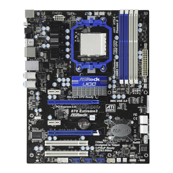
Page 12: Motherboard Layout
Chassis Fan Connector (CHA_FAN2) HDMI_SPDIF Header Chassis Fan Connector (CHA_FAN3) (HDMI_SPDIF1, White) Northbridge Controller PCI Express 2.0 x16 Slot (PCIE4; Blue) SPI Flash Memory (32Mb) PCI Express 2.0 x1 Slot (PCIE3; White) Southbridge Controller PCI Slot (PCI1) SATA3 Connector (SATA3_4_5, White) PCI Express 2.0 x16 Slot (PCIE2;... -
Page 13: I/O Panel
Coaxial SPDIF Out Port ** 8 Front Speaker (Lime) PS/2 Keyboard Port (Purple) Microphone (Pink) * There are two LED next to the LAN port. Please refer to the table below for the LAN port LED indications. LAN Port LED Indications ACT/LINK SPEED... - Page 14 To enable Multi-Streaming function, you need to connect a front panel audio cable to the front panel audio header. After restarting your computer, you will find “Mixer” tool on your system. Please select “Mixer ToolBox” , click “Enable playback multi-streaming”, and click “ok”.
-
Page 15: Installation
Installation Installation Installation This is an ATX form factor (12.0-in x 9.6-in, 30.5 cm x 24.4 cm) motherboard. Before you install the motherboard, study the configuration of your chassis to en- sure that the motherboard fits into it. Pre-installation Precautions... -
Page 16: Cpu Installation
Step 4. When the CPU is in place, press it firmly on the socket while you push down the socket lever to secure the CPU. The lever clicks on the side tab to indicate that it is locked. -
Page 17: Installation Of Memory Modules (Dimm)
(the same brand, speed, size and chip- type) DDR3 DIMM pair in the slots of the same color. In other words, you have to install identical DDR3 DIMM pair in Dual Channel A (DDR3_A1 and DDR3_B1;... - Page 18 DIMMs or the system components. Step 1. Unlock a DIMM slot by pressing the retaining clips outward. Step 2. Align a DIMM on the slot such that the notch on the DIMM matches the break on the slot. notch break...
-
Page 19: Expansion Slots (Pci And Pci Express Slots)
2.4 Expansion Slots (PCI and PCI Express Slots) 2.4 Expansion Slots (PCI and PCI Express Slots) There are 2 PCI slots and 4 PCI Express slots on this motherboard. PCI Slots: PCI slots are used to install expansion cards that have the 32-bit PCI interface. PCIE Slots: PCIE1 / PCIE3 (PCIE x1 slot;... -
Page 20: Tm Tm
2.5.1 Graphics Card Setup Different CrossFireX cards may require different methods to enable CrossFireX feature. In below procedures, we use Radeon HD 3870 as the example graphics card. For other CrossFireX cards that ATI has released or will release in the future, please refer to ATI graphics card manuals for detailed installation guide. - Page 21 Step 3. Connect the DVI monitor cable to the DVI connector on the Radeon graphics card on PCIE2 slot. (You may use the DVI to D-Sub adapter to convert the DVI connector to D-Sub interface, and then connect the D-Sub monitor...
- Page 22 Install the CATALYST Control Center. Please check AMD website for details. Step 4. Restart your computer. Step 5. Install the VGA card drivers to your system, and restart your computer. ® Then you will find “ATI Catalyst Control Center” on your Windows taskbar.
- Page 23 * CrossFireX appearing here is a registered trademark of ATI Technologies Inc., and is used only for identification or explanation and to the owners’ benefit, without intent to infringe. * For further information of ATI CrossFireX technology, please check AMD website for...
-
Page 24: Surround Display Feature
CLRCMOS1 for 5 seconds. However, please do not clear the CMOS right after you update the BIOS. If you need to clear the CMOS when you just finish updating the BIOS, you must boot up the system first, and then shut it down... -
Page 25: Onboard Headers And Connectors
2.8 Onboard Headers and Connectors Onboard headers and connectors are NOT jumpers. Do NOT place jumper caps over these headers and connectors. Placing jumper caps over the headers and connectors will cause permanent damage of the motherboard! Serial ATA3 Connectors... - Page 26 HDA to function correctly. Please follow the instruction in our manual and chassis manual to install your system. 2. If you use AC’97 audio panel, please install it to the front panel audio header as below: A.
- Page 27 Though this motherboard provides 4-Pin CPU fan (Quiet Fan) support, the 3-Pin CPU fan still can work successfully even without the fan speed control function. If you plan to connect the 3-Pin CPU fan to the CPU fan connector on this motherboard, please connect it to Pin 1-3.
- Page 28 Though this motherboard provides 8-pin ATX 12V power connector, it can still work if you adopt a traditional 4-pin ATX 12V power supply. To use the 4-pin ATX power supply, please plug your power supply along with Pin 1 and Pin 5.
-
Page 29: Smart Switches
CMOS values (see p.13 No. 14) You are not allowed to use Clear CMOS switch function if you set up the system password. If you want to clear the CMOS values, please clean your system password in advance or refer to page 24 “Clear CMOS jumper” description... -
Page 30: Dr. Debug
2.10 Dr. Debug 2.10 Dr. Debug 2.10 Dr. Debug 2.10 Dr. Debug Dr. Debug is used to provide code information, which makes troubleshooting even easier. Please see the diagrams below for reading the Dr. Debug codes. Status Code Description 0x00... - Page 31 Internal CPU error 0x5B reset PPI is not available 0x5C-0x5F Reserved for future AMI error codes 0xE0 S3 Resume is stared (S3 Resume PPI is called by the DXE IPL) 0xE1 S3 Boot Script execution 0xE2 Video repost 0xE3 OS S3 wake vector call...
- Page 32 North Bridge DXE initialization is started 0x6A North Bridge DXE SMM initialization is started 0x6B North Bridge DXE initialization (North Bridge module specific) 0x6C North Bridge DXE initialization (North Bridge module specific) 0x6D North Bridge DXE initialization (North Bridge module specific)
- Page 33 0xA7 SCSI Enable 0xA8 Setup Verifying Password 0xA9 Start of Setup 0xAA Reserved for ASL (see ASL Status Codes section below) 0xAB Setup Input Wait 0xAC Reserved for ASL (see ASL Status Codes section below) 0xAD Ready To Boot event...
-
Page 34: Serial Ata3 (Sata3) Hard Disks Installation
SATA3 HDD. What is Hot Swap Function? If SATA3 HDDs are built as RAID 1 or RAID 5 then it is called “Hot Swap” for the action to insert and remove the SATA3 HDDs while the system is... -
Page 35: Sata3 Hdd Hot Plug Feature And Operation Guide
3. Please make sure the SATA3 driver is installed into system properly. The latest SATA3 driver is available on our support website: www.asrock.com 4. Make sure to use the SATA power cable & data cable, which are from our motherboard package. - Page 36 How to Hot Plug a SATA3 HDD: Points of attention, before you process the Hot Plug: Please do follow below instruction sequence to process the Hot Plug, improper procedure will cause the SATA3 HDD damage and data loss. Step 1...
-
Page 37: Driver Installation Guide
2.14 Driver Installation Guide To install the drivers to your system, please insert the support CD to your optical drive first. Then, the drivers compatible to your system can be auto-detected and listed on the support CD driver page. Please follow the order from up to bottom side to install those required drivers. -
Page 38: With Raid Functions
F6 to install a third-party RAID driver. When prompted, insert the SATA3 driver diskette containing the AMD RAID driver. After reading the floppy disk, the driver will be presented. Select the driver to install according to the OS you install. -
Page 39: Installing Windows
F6 to install a third-party AHCI driver. When prompted, insert the SATA3 driver diskette containing the AMD AHCI driver. After reading the floppy disk, the driver will be presented. Select the driver to install according to the OS you install. -
Page 40: Installing Windows
Untied Overclocking function, please enter “Overclock Mode” option of UEFI setup to set the selection from [Auto] to [Manual]. Therefore, CPU FSB is untied during overclocking, but PCI / PCIE buses are in the fixed mode so that FSB can operate under a more stable overclocking environment. -
Page 41: Uefi S
This section explains how to use the UEFI SETUP UTILITY to configure your system. The SPI Memory on the motherboard stores the UEFI SETUP UTILITY. You may run the UEFI SETUP UTILITY when you start up the computer. Please press <F2> or <Del>... -
Page 42: Navigation Keys
Main Screen Main Screen Main Screen Main Screen When you enter the UEFI SETUP UTILITY, the Main screen will appear and display the system overview. System Time [Hour:Minute:Second] Use this item to specify the system time. System Date [Day Month/Date/Year]... - Page 43 ASRock UCC ASRock UCC (Unlock CPU Core) feature simplifies AMD CPU activation. As long as a simple switch of the UEFI option “ASRock UCC”, you can unlock the extra CPU core to enjoy an instant performance boost. When UCC feature is enabled, the dual-core or triple-core CPU will boost to the quad-...
- Page 44 Multiplier/Voltage Change This item is set to [Auto] by default. If it is set to [Manual], you may adjust the value of Processor Frequency and Processor Voltage. However, it is recommended to keep the default value for system stability. CPU Frequency (MHz) Use this option to adjust CPU frequency.
-
Page 45: Oc Tweaker Screen
Channel Interleaving It allows you to enable Channel Memory Interleaving. Configuration options: [Disabled], [Address bits 6], [Address bits 12], [HASH 1] and [HASH 2]. The default value is [HASH 2]. CAS# Latency (tCL) Use this item to change CAS# Latency (tCL) Auto/Manual setting. - Page 46 SB Core Voltage Use this to select SB Core Voltage. The default value is [Auto]. Would you like to save current setting user defaults? In this option, you are allowed to load and save three user defaults according to your own requirements.
-
Page 47: Advanced Screen
MS-DOS or Windows . Just launch this tool and save the new UEFI file to your USB flash drive, floppy disk or hard drive, then you can update your UEFI only in a few clicks without preparing an additional floppy diskette or other complicated flash utility. -
Page 48: Cpu Configuration
In the C1 power state, the processor maintains the context of the system caches. CPU Thermal Throttle Use this item to enable CPU internal thermal control mechanism to keep the CPU from overheated. The default value is [Auto]. -
Page 49: South Bridge Configuration
Primary Graphics Adapter This item will switch the PCI Bus scanning order while searching for video card. It allows you to select the type of Primary VGA in case of multiple video controllers. The default value of this feature is [PCI Express]. -
Page 50: Storage Configuration
Use this item to enable or disable the “SATA Controller” feature. SATA Mode Use this item to adjust SATA Mode. The default value of this option is [IDE Mode]. Configuration options: [AHCI Mode], [RAID Mode] and [IDE Mode]. If you set this item to RAID mode, it is suggested to install SATA ODD driver on SATA3_5 port. -
Page 51: Super Io Configuration
Serial Port Use this item to enable or disable the onboard serial port. Serial Port Address Use this item to set the address for the onboard serial port. Configuration options: [Auto], [3F8 / IRQ4] and [3E8 / IRQ4]. Infrared Port Use this item to enable or disable the onboard infrared port. -
Page 52: Acpi Configuration
Use this item to enable or disable PS/2 keyboard to turn on the system from the power-soft-off mode. PCI Devices Power On Use this item to enable or disable PCI devices to turn on the system from the power-soft-off mode. Ring-In Power On Use this item to enable or disable Ring-In signals to turn on the system from the power-soft-off mode. -
Page 53: Usb Configuration
3.4.6 3.4.6 USB Configuration USB 2.0 Controller Use this item to enable or disable the use of USB 2.0 controller. USB 3.0 Controller Use this item to enable or disable the use of USB 3.0 controller. Legacy USB Support Use this option to select legacy support for USB devices. There are four confi guration options: [Enabled], [Auto], [Disabled] and [UEFI Setup Only]. -
Page 54: Hardware Health Event Monitoring Screen
Hardware Health Event Monitoring Screen Hardware Health Event Monitoring Screen In this section, it allows you to monitor the status of the hardware on your system, including the parameters of the CPU temperature, motherboard temperature, CPU fan speed, chassis fan speed, and the critical voltage. -
Page 55: Boot Screen
Boot Screen Boot Screen Boot Screen In this section, it will display the available devices on your system for you to config- ure the boot settings and the boot priority. Setup Prompt Timeout This shows the number of seconds to wait for setup activation key. -
Page 56: Security Screen
3.7 Security Screen Security Screen Security Screen Security Screen Security Screen In this section, you may set or change the supervisor/user password for the system. For the user password, you may also clear it. -
Page 57: Exit Screen
When you select this option, it will pop-out the following message, “Dis- card changes?” Select [OK] to discard all changes. Load UEFI Defaults Load UEFI default values for all the setup questions. F9 key can be used for this operation. Launch EFI Shell from filesystem device Attempts to Launch EFI Shell application (Shell64.efi) from one of the... -
Page 58: Software Support Software Support
4.2.1 Running The Support CD 4.2.1 Running The Support CD To begin using the support CD, insert the CD into your CD-ROM drive. The CD automatically displays the Main Menu if “AUTORUN” is enabled in your computer. If the Main Menu did not appear automatically, locate and double click on the file “ASSETUP.EXE”... -
Page 59: Installing Os On A Hdd Larger Than 2Tb
2. Set AHCI Mode in UEFI Setup Utility > Advanced > Storage Configuration > SATA Mode. 3. Press F11 to launch boot menu at system POST. 4. Choose the item “UEFI:xxx“ to boot. (“xxx” is the device which contains your Windows ®...
Need help?
Do you have a question about the 870 EXTREME3 and is the answer not in the manual?
Questions and answers