Table of Contents
Advertisement
Quick Links
Advertisement
Chapters
Table of Contents

Subscribe to Our Youtube Channel
Related Manuals for Purelogic ESVZAD0


Summary of Contents for Purelogic ESVZAD0
- Page 1 USER MANUAL ESVZAD0 DeviceNet module...
-
Page 2: Table Of Contents
Contents Cyclic Data Access ............................18 What is Cyclic Data? ........................18 Mapping Cyclic Data ........................18 5.2.1 Data OUT .........................18 5.2.2 Data IN ..........................18 Input/Output Assembly Configuration Mappings ................19 5.3.1 Output Assembly Details ....................19 5.3.2 Input Assembly Details ....................22 Troubleshooting and Fault Elimination ......................25 Faults ............................25 Troubleshooting ..........................25 Reference ..............................26... - Page 3 Safety Information Safety Information 1.1 Warnings, Cautions and Notes 1.1.1 General Some parts of Lenze controllers (frequency inverters, servo inverters, DC controllers) can be live, moving and rotating. Some surfaces can be hot. Non-authorized removal of the required cover, inappropriate use, and incorrect installation or operation creates the risk of severe injury to personnel or damage to equipment. All operations concerning transport, installation, and commissioning as well as maintenance must be carried out by qualified, skilled personnel (IEC 364 and CENELEC HD 384 or DIN VDE 0100 and IEC report 664 or DIN VDE0110 and national regulations for the prevention of accidents must be observed).
- Page 4 Safety Information 1.1.5 Operation Systems including controllers must be equipped with additional monitoring and protection devices according to the corresponding standards (e.g. technical equipment, regulations for prevention of accidents, etc.). The user is allowed to adapt the controller to his application as described in the regulatory documentation. DANGER! •...
- Page 5 Introduction Introduction The following information is provided to allow the SMV Series drive to operate on a DeviceNet network; it is not intended to explain how DeviceNet™ itself works. Therefore, a working knowledge of DeviceNet is assumed, as well as familiarity with the operation of the SMV Series drive. 2.1 Fieldbus Overview The DeviceNet fieldbus is an internationally accepted communications protocol designed for commercial and...
- Page 6 ESVZAD0-000XX1A10 Fieldbus Identifier: D0 = DeviceNet Left-hand Label: Module Data A: Fieldbus Protocol SMV DeviceNet B: Model Number TYPE: ESVZAD0 C: Lenze Order Number ID-NO: 12345678 D: Firmware Revision ESVZAD0-000XX1A10 E: Hardware Revision Figure 1: SMV DeviceNet Module Label CMVDVN01B...
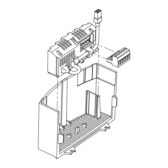
- Page 7 Installation Installation 3.1 Mechanical Installation 1. Ensure that for safety reasons, the AC supply has been disconnected before opening the terminal cover. 2. Insert the DeviceNet option module in the terminal cover and securely "click" into position as illustrated in Figure 2. 3.
- Page 8 Installation 3.2 DeviceNet Terminal Block Table 2: DeviceNet Pin Assignments Terminal Name Wire Color Description Terminal Block Black CAN_L Blue CAN Bus Low (negative data line) Shield Bare CAN_H White CAN Bus High (positive data line) 11 - 25 VDC power supply; current consumption (100mA @ 11VDC max) 3.3 Electrical Installation...
- Page 9 Installation • Use fiber optic segments to: • Extend networks beyond normal cable limitations • Overcome different ground potential problems • Overcome very high electromagnetic interference • Ground at only one location, preferably in the center of the network. 3.3.3 Connections and Shielding •...
- Page 10 Installation 3.3.4 Network Termination In high speed fieldbus networks such as DeviceNet, it is essential to install the specified termination resistors, i.e. one at both ends of a network segment. Failure to do so will result in signals being reflected back along the cable which will cause data corruption.
- Page 11 Commissioning Commissioning DeviceNet Communication 4.1 Overview It is assumed that the user has familiarised themselves with how to navigate through the drive parameters using the keypad. Refer to the drive user manual for details. The details that follow provide a step-by-step guide to quickly and easily set-up an SMV drive to communicate on a DeviceNet fieldbus network, in a basic format.
- Page 12 Commissioning 4.3 Configuring the SMV DeviceNet Module 4.3.1 Connecting With the drive power disconnected install the DeviceNet module and connect the network cable as instructed in the preceeding section 3.1. Ensure the drive Run/Enable terminal is disabled then apply the correct voltage to the drive (refer to the drive's user manual for voltage supply details).
- Page 13 Commissioning 4.3.4 Baud / Data Rate P411 - Baud Rate Default: Range: 0 - 2 Access: Type: Integer Set P411 to match the DeviceNet network baud rate. Table 4: DeviceNet Baud Rates P411 Value Baud Rate 125 kbps 250 kbps 500 kbps NOTE: If P411 (BAUD RATE) has been changed, the drive must be reset by recycling power or by issuing a RESET command using Parameter P418 via the DeviceNet network before the new value takes effect.
- Page 14 Commissioning 4.3.6 Data Mapping • The SMV DeviceNet module has support for 1 cyclic data channel in both directions. • Cyclic data configuration is described in detail in section 5. • The default mapping for SMV DeviceNet is 2 Data IN words and 2 Data OUT words, the configuration is shown in Table 6.
- Page 15 Commissioning 4.3.8 Check Node Status P419 - DeviceNet Status Default: Range: 0 - 4 Access: Type: Integer P419 is a 4-digit integer. Digit 1 represents the Power Status, Digit 2 the Control Status, Digit 3 the Network Status and Digit 4 the I/O Status. Refer to Table 7 for the DeviceNet Status description. Table 7: DeviceNet Module Status P419 Digit Digit Represnts Selection...
- Page 16 Commissioning P400 DEVICENET NODE ADDRESS (0 - 63) P401 DEVICENET BAUD RATE (125, 250, 500 kbps) P430 DEVICENET OUTPUT ASSEMBLY SELECTION - Set this parameter to select output assembly for Polled connection. The following selections are available: 0 = 20 Basic Speed Control 1 = 21 Extended Speed Control RPM 2 = 100 Extended Speed Control Hz + Digital and Analog Output 1 3 = 102 PID Setpoint + Digital + Analog Output 1...
-
Page 17: Cyclic Data Access
Cyclic Data Access Cyclic Data Access 5.1 What is Cyclic Data? • Cyclic/Process/Polled data is the name given to the method used to transfer routine process data between the network master and slave nodes. • Cyclic data transfer must be configured during network setup. • The terms “OUT data” and “IN data” describe the direction of data transfer as seen by the DeviceNet network master controller. -
Page 18: Input/Output Assembly Configuration Mappings
Cyclic Data Access 5.3 Input/Output Assembly Configuration Mappings 5.3.1 Output Assembly Details P430 = 0: Output Assembly 20 Basic Speed Control P430 = 1: Output Assembly 21 Extended Speed Control P430 = 0 P430 = 1 0 = NOT Run Forward 0 = NOT Run Forward 1 = Run Forward 1 = Run Forward 0 = NOT Run Reverse Reserved... - Page 19 Cyclic Data Access P430 = 2: Output Assembly 100 Speed in Hz + Digital and Analog Output P430 = 3: Output Assembly 102 PID Setpoint + Digital and Analog Output P430 = 2 P430 = 3 0 = NOT Run Forward 0 = NOT Run Forward 1 = Run Forward 1 = Run Forward 0 = NOT Run Reverse...
- Page 20 Cyclic Data Access P430 = 4: Output Assembly 104 Torque Setpoint + Digital and Analog Output P430 = 4 0 = NOT Run Forward 1 = Run Forward 0 = NOT Run Reverse 1 = Run Reverse Fault reset on transition from 0 to 1 Reserved Reserved 0 = Local Control...
-
Page 21: Input Assembly Details
Cyclic Data Access 5.3.2 Input Assembly Details P440 = 0: Input Assembly 70 Basic Speed Control P440 = 1: Input Assembly 71 Extended Speed Control P440 = 0 P440 = 1 1 = Faulted 1 = Faulted Reserved Reserved 1 = Running Forward 1 = Running Forward Reserved 1 = Running Reverse Reserved... - Page 22 Cyclic Data Access P440 = 2: Input Assembly 101 Speed in Hz + Digital and Analog Input P440 = 3: Input Assembly 103 Speed in Hz + Actual PID Setpoint and Feedback P440 = 2 P440 = 3 1 = Faulted 1 = Faulted Reserved Reserved 1 = Running Forward...
- Page 23 Cyclic Data Access P440 = 4: Input Assembly 105 Speed in Hz + Actual Torque and Analog Input P440 = 5: Input Assembly 106 Custom Selectable P440 = 4 P440 = 5 1 = Faulted Reserved 1 = Running Forward 1 = Running Reverse 1 = Ready 0 = Local Control 1 = Network Control...
-
Page 24: Troubleshooting And Fault Elimination
Troubleshooting & Fault Elimination Troubleshooting and Fault Elimination 6.1 Faults Table 10 lists the faults common to the DeviceNet Communications Module. Table 10: Faults STATUS POSSIBLE CAUSE REMEDY Module to Drive com- Connection between drive and module is Check cable and connection between F.ntF munication timeout not made. -
Page 25: Reference
Reference Reference Refer to the Installation and Operation manual (SV01) for drive-specific parameters. The 400 Series parameters exclusive to the DeviceNet™ communications module are accessible once the DeviceNet module is installed. 7.1 P400 Parameter Menu Code Possible Settings IMPORTANT Name Default Selection CANopen Module Specific Parameters 0 Not Active P400 Network Protocol... - Page 26 Reference Code Possible Settings IMPORTANT Name Default Selection 0 Trigger fault 'F_nt1' Action on Loss of 1 Ignore P415 DeviceNet 2 AC Tech specific - Switch off network Only active in Network Control (n.xxx) controlled bits (STOP is not triggered) 0 Hold in Error P416 Bus Off 1 Reset CAN...
- Page 27 Reference Code Possible Settings IMPORTANT Name Default Selection Assembly Configuration Parameters 0 Output assembly 20 - basic speed control Length = 4 bytes 1 Output assembly 21 - extended speed control Length = 4 bytes DeviceNet Output Assembly 2 Output assembly 100 - extended speed Hz + Length = 8 bytes P430 Selection...
- Page 28 Reference Code Possible Settings IMPORTANT Name Default Selection DeviceNet Configuration Parameters 0 Nonexistent Read-only 1 Configuring 2 Wait for connection ID Explicit Message P450 Instance State 3 Established 4 Timed out 5 Deferred delete Explicit Message P452 Expected Packet 0 ... 65535 {ms} Read-only Rate Explicit Message...
- Page 29 Reference Code Possible Settings IMPORTANT Name Default Selection Bit Strobe P472 Expected Packet 0 ... 65535 {ms} Read-only Rate 0 Transition to timed out - stays in timeout Read-only Bit Strobe Status 1 Auto delete - goes into nonexistent state Bit Info Bit 0,1: 2 Auto reset - reset the connection timeout timer...
- Page 30 Reference Code Possible Settings IMPORTANT Name Default Selection Change of State Value from WORD selected in P485 P486 0 ... 65535 Status (16-bits) Read-only Read/write Change of State Note: State change of bits in P486 masked with P487 Bit Mask (16- 65535 0 ...
-
Page 31: Class Implementation Details
Reference 7.2 Class Implementation Details 7.2.1 Identity Object - Class 0x01 IDENTITY CLASS ATTRIBUTES ATTRIBUTE ID ACCESS RULE NAME DATA TYPE VALUE INSTANCE 0 REVISION UINT INSTANCE 1 VENDOR ID UINT DEVICE TYPE UINT 2 (AC drive) PRODUCT CODE UINT 2 (SMV DeviceNet Module) MAJOR REV. USINT MINOR REV. USINT 4 = Configured STATUS USINT 5 = Owned... -
Page 32: Devicenet Object - Class 0X03
Reference 7.2.3 DeviceNet Object - Class 0x03 DEVICENET CLASS ATTRIBUTES ATTRIBUTE ID ACCESS RULE NAME DATA TYPE VALUE INSTANCE 0 REVISION UINT INSTANCE 1 GET/SET NODE ADDRESS USINT 0 to 63 GET/SET DATA RATE USINT 0 to 2 GET/SET BOOL 0 = Hold in Error 1 = Reset CAN GET/SET BUS-OFF COUNTER USINT... -
Page 33: Assembly Object - Class 0X04
Reference 7.2.4 Assembly Object - Class 0x04 ASSEMBLY CLASS ATTRIBUTES ATTRIBUTE ID ACCESS RULE NAME DATA TYPE VALUE INSTANCE 0 REVISION UINT MAXIMUM NUMBER OF INSTANCES USINT INSTANCES (See Below) NUMBER OF MEMBER USINT GET/SET DATA INSTANCE INSTANCE NUMBER AND NAME ACCESS RULE FOR ATTRIBUTE #3 DATA INSTANCE 20 = BASIC SPEED CONTROL GET / SET INSTANCE 21 = EXTENDED SPEED CONTROL GET / SET INSTANCE 100 = EXTENDED SPEED HZ + DIGITAL AND ANALOG OUTPUT GET / SET... -
Page 34: Devicenet Connection Object - Class 0X05
Reference 7.2.5 DeviceNet Connection Object - Class 0x05 DEVICENET CONNECTION CLASS ATTRIBUTES ATTRIBUTE ID ACCESS RULE NAME DATA TYPE VALUE INSTANCE 0 REVISION UINT INSTANCE 1 - EXPLICIT MESSAGE INSTANCE 0 = Nonexistent 1 = Configuring STATE USINT 3 = Established 4 = Timed Out 5 = Deferred Delete INSTANCE TYPE USINT 0 = Explicit TRANSPORT CLASS TRIGGER... - Page 35 Reference DEVICENET CONNECTION CLASS ATTRIBUTES ATTRIBUTE ID ACCESS RULE NAME DATA TYPE VALUE INSTANCE 2 - POLLED I/O MESSAGE CONNECTION 0 = Nonexistent 1 = Configuring STATE USINT 3 = Established 4 = Timed Out INSTANCE TYPE USINT 1 = I/O Connection TRANSPORT CLASS USINT 0x82 TRIGGER PRODUCED UINT...
- Page 36 Reference DEVICENET CONNECTION CLASS ATTRIBUTES ATTRIBUTE ID ACCESS RULE NAME DATA TYPE VALUE INSTANCE 3 - BIT STROBE STATE USINT 0 = Nonexistent 1 = Configuring 3 = Established 4 = Timed Out INSTANCE TYPE USINT 1 = I/O Connection TRANSPORT CLASS USINT 0x82 TRIGGER PRODUCED UINT CONNECTION ID CONSUMED...
- Page 37 Reference DEVICENET CONNECTION CLASS ATTRIBUTES ATTRIBUTE ID ACCESS RULE NAME DATA TYPE VALUE INSTANCE 4 - CHANGE OF STATE / CYCLIC INSTANCE 0 = Nonexistent 1 = Configuring STATE USINT 3 = Established 4 = Timed Out INSTANCE TYPE USINT 1 = I/O Connection TRANSPORT CLASS USINT 0x82 TRIGGER...
-
Page 38: Parameter Object - Class 0X0F
Reference 7.2.6 Parameter Object - Class 0x0F PARAMETER CLASS ATTRIBUTES NUMBER OF INSTANCES (PARAMETERS): 550 ATTRIBUTE ID ACCESS RULE NAME DATA TYPE VALUE INSTANCE 0 REVISION UINT NUMBER OF INSTANCES UINT PARAMETER CLASS WORD 0x03 DESCRIPTOR CONFIGURATION UINT ASSEMBLY # NATIVE LANGUAGE UINT 0 = English INSTANCE 1 - 550 GET / SET PARAMETER VALUE LINK PATH SIZE USINT... - Page 39 Reference Parameter Object Instance (Parameter List) NOTE: These same parameters are present in the EDS File ID NO PARAMETER OBJECT MAPPING 1-49 RESERVED DIGITAL OUTPUT BITS 0x0F-50-1 51-54 RESERVED TB30 ANALOG OUTPUT 0x0F-55-1 56-59 RESERVED KEYPAD COMMAND FREQUENCY 0x0F-60-1 NETWORK COMMAND FREQUENCY 0x0F-61-1 ACTUAL COMMAND FREQUENCY 0x0F-62-1...
-
Page 40: Digital Output Bits 0X0F-50-1
Reference PARAMETER ATTRIBUTES ATTRIBUTE ID ACCESS RULE BIT # ATTRIBUTE GET/SET Digital Output Bits TB14 Out State ( 1 - ON; 0 - OFF) Relay State ( 1 - ON; 0 - OFF) GET/SET Min/Max (0/1000) corresponds to 0.00 to 10.00VDC TB30 Analog Output GET/SET Min/Max (0.0/500.0) Hz Keypad Command Frequency... -
Page 41: Reserved
Reference PARAMETER ATTRIBUTES ATTRIBUTE ID ACCESS RULE BIT # ATTRIBUTE GET/SET 0 = NOT Run Forward Control Word 1 = Run Forward 0 = NOT Run Reverse 1 = Run Reverse Fault reset on transition from 0 to 1 Reserved Reserved 0 = Local Control 1 = Network Control 0 = Local Speed Ref 1 = Network Speed Ref... -
Page 42: Devicenet Status Word
Reference PARAMETER ATTRIBUTES ATTRIBUTE ID ACCESS RULE BIT # ATTRIBUTE Read Only 1 = Faulted DeviceNet Status Word Reserved 1 = Running Forward 1 = Running Reverse 1 = Ready 0 = Local Control 1 = Network Control 0 = Local Speed Ref 1 = Network Speed Ref 1 = At Reference Network Speed Reference (valid if bit 6 is set) 0 = Keypad... -
Page 43: Drive Operation State
Reference PARAMETER ATTRIBUTES ATTRIBUTE ID ACCESS RULE BIT # ATTRIBUTE Read Only 0 = Stop Drive Status Word 1 = Run 1 = Quick Stop (ramp to stop) Active 0 = Direction Forward (commanded) 1 = Direction Reverse 0 = Direction Forward (actual) 1 = Direction Reverse 0 = NET REF not active 1 = NET REF sets the active source 0 = Speed Mode... -
Page 44: Present Fault
Reference PARAMETER ATTRIBUTES ATTRIBUTE ID ACCESS RULE BIT # ATTRIBUTE Read Only Temperature Output Fault Present Fault Overcurrent Fault Ground (Short to Earth) Fault Excessive Drive Temperature Fault Fly Start Fault High Bus Voltage (Over Voltage) Fault Low Bus Voltage Fault Motor Overload Fault OEM Defaults Corrupted Illegal Setup Fault Dynamic Brake Overheated Fault... - Page 45 Reference PARAMETER ATTRIBUTES ATTRIBUTE ID ACCESS RULE BIT # ATTRIBUTE Internal Fault (Module Communication (SPI) Timeout) Present Fault Internal Fault (FNR: Invalid Message Received) (continued) Network Fault #1 Network Fault #2 Network Fault #3 Network Fault #4 Network Fault #5 Network Fault #6 Network Fault #7 Network Fault #8 Network Fault #9 GET/SET...
-
Page 46: Parameter Group Object - Class 0X10
Reference 7.2.7 Parameter Group Object - Class 0x10 PARAMETER GROUP CLASS ATTRIBUTES ATTRIBUTE ID ACCESS RULE NAME DATA TYPE VALUE INSTANCE 0 REVISION UINT NUMBER OF INSTANCES UINT NATIVE LANGUAGE UINT 0 = English INSTANCE 1 - 3 GROUP NAME SHORT STRING NUMBER OF MEMBERS UINT IN THE GROUP 1st PARAMETER UINT IN THE GROUP 2nd PARAMETER... -
Page 47: Control Supervisor Object - Class 0X29
Reference 7.2.9 Control Supervisor Object - Class 0x29 CONTROL CLASS ATTRIBUTES ATTRIBUTE ID ACCESS RULE NAME DATA TYPE VALUE INSTANCE 0 REVISION UINT NUMBER OF INSTANCES UINT INSTANCE 1 NUMBER OF SUPPORTED USINT ATTRIBUTES ATTRIBUTE LIST ARRAY GET/SET RUNFWD BOOL 0 to 1 GET/SET RUNREV BOOL 0 to 1 GET/SET NETCTRL BOOL 0 to 1... - Page 48 Reference FAULT CODES Fault Code Fault Number Fault Description 0x0000 NO FAULT 0x2220 Temperature Output Fault 0x2220 Over Current Fault 0x2240 Ground (Short to Earth) Fault 0x4310 Excess Drive Temperature Fault 0x0000 Fly Start Fault 0x3210 High Bus Voltage (Over Voltage) Fault 0x3220 Low Bus Voltage (Under Voltage) Fault 0x7122 Motor Overload Fault 0x6320...
- Page 49 Reference FAULT CODES Fault Code Fault Number Fault Description 0x7500 Internal Communication from JK1 Lost Fault 0x7501 Internal Fault (Module Communication (SPI) Timeout) 0x7502 Internal Fault (FNR: Invalid Message Received) 0x7511 Network Fault #1 0x7512 Network Fault #2 0x7513 Network Fault #3 0x7514 Network Fault #4 0x7515 Network Fault #5 0x7516...
-
Page 50: Ac/Dc Drive Object - Class 0X2A
Reference 7.2.10 AC/DC Drive Object - Class 0x2A AC/DC DRIVE CLASS ATTRIBUTES Attribute ID Access Rule Name Data Type Value INSTANCE 0 REVISION UINT NUMBER OF INSTANCES UINT INSTANCE 1 NO. OF SUPPORTED ATTRIBUTES USINT ATRIBUTE LIST ARRAY AT REFERENCE BOOL Speed AtRef 0 = Local SpdRef GET/SET NET REFERENCE BOOL 1 = Net SpdRef 1 = Open Loop Spd Control 2 = Vector Mode... -
Page 51: Acknowledge Handler Object - Class 0X2B
Reference 7.2.11 Acknowledge Handler Object - Class 0x2B ACKNOWLEDGE HANDLER CLASS ATTRIBUTES Attribute ID Access Rule Name Data Type Value INSTANCE 0 REVISION UINT NUMBER OF INSTANCES UINT INSTANCE 1 GET/SET ACKNOWLEDGE TIMER UINT 1 to 65535 ms GET/SET RETRY LIMIT USINT 0 to 255 COS PRODUCING CONN INSTANCE UINT ACKNOWLEDGE HANDLER CLASS SERVICES Service Code Implemented For Service Name... - Page 52 www. p ur e l o g i c . r u C o n t a c t s + 7 ( 4 9 5 ) 5 0 5 - 6 3 - 7 4 - Mo s c o w + 7 ( 4 7 3 ) 2 0 4 - 5 1 - 5 6 - V o r o n e z h w w w .
Need help?
Do you have a question about the ESVZAD0 and is the answer not in the manual?
Questions and answers