Table of Contents
Advertisement
Service
Manual
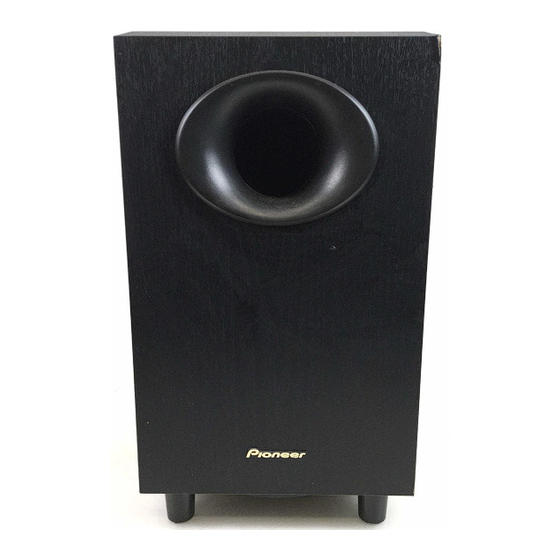
POWERED SUBWOOFER
S-W20
PIONEER CORPORATION
PIONEER ELECTRONICS SERVICE, INC.
©
PIONEER CORPORATION 2000
CONTENTS
1. SAFETY INFORMATION ............................................. 2
2. DISASSEMBLY ............................................................ 3
5. PCB CONNECTION DIAGRAM ................................. 10
6. PCB PARTS LIST ...................................................... 13
7. ADJUSTMENT ........................................................... 15
8. PANEL FACILITIES .................................................... 16
9. SPECIFICATIONS ....................................................... 17
4-1, Meguro 1-Chome, Meguro-ku, Tokyo 153-8655, Japan
P.O.Box 1760, Long Beach, CA 90801-1760, U.S.A.
S-W20-K
ORDER NO.
PET99021
1
Advertisement
Table of Contents

Summary of Contents for Pioneer S-W20
-
Page 1: Table Of Contents
6. PCB PARTS LIST ............13 7. ADJUSTMENT ............15 8. PANEL FACILITIES ............ 16 9. SPECIFICATIONS ............17 PIONEER CORPORATION 4-1, Meguro 1-Chome, Meguro-ku, Tokyo 153-8655, Japan PIONEER ELECTRONICS SERVICE, INC. P.O.Box 1760, Long Beach, CA 90801-1760, U.S.A. © PIONEER CORPORATION 2000... -
Page 2: Safety Information
The use of a substitute replacement component which does Leakage 0.5mA current Device not have the same safety characteristics as the PIONEER tester under recommended replacement one, shown in the parts list in test this Service Manual, may create shock, fire, or other hazards. -
Page 3: Disassembly
S-W20 2. DISASSEMBLY POWER AMP SECTION • Remove the 8 screws from the power amplifier. • Remove the connector lead, etc. PLASTIC COVER • The plastic cover is attached to the cabinet by its bosses applied with adhesive. To detach it, pry it open by inserting a flat blade scewdriver between the cabinet and the grille. - Page 4 S-W20 3.2 EXTERIOR SECTION Parts List Mark No. Description Parts No. Cabinet Enclosure 272562 Amplifier Assembly 272537 Plastic Cover 272428 Paper Port Tube 272557 Front Port Ring 275823 Rear Port Ring Assembly 275858 Transducer 272542 Foot 255116 Logo 267189 Screw (for Foot) 222539 Screw (for Amplifier and Trans.)
- Page 5 S-W20 3.3 POWER AMP SECTION NOTES : ÷ Parts marked by “ NSP ” are generally unavailable because they are not in our Master Spare Parts List. ÷ The mark found on some component parts indicates the importance of the safety factor of the part.
-
Page 6: Schematic And Pcb Connection Diagrams
S-W20 4. BLOCK DIAGAM AND SCHEMATIC DIAGRAM 4.1 BLOCK DIAGRAM OPERATON Gain Adj Photo ASSY : AWU7541 MAIN Volume Coupler +16v +6 V PC41 TLP621(Y) IC 201 L. P. F. H. P. F. NJM2904M JA201 Line Q201 Buff Buff Level... - Page 7 S-W20 +84v Charge balance and DC feedback Power Speaker Over Voltage Buff Detection C13, C14 - 84v Signal feedback Clip Det. AMP ASSY : AWU7540 DTA124EK Ó Slow ON/OFF 168v Mute Start − Ó G3SBA20L Thermal Detection IRF640 34.5dBv Total Gain...
- Page 8 S-W20 4.2 AMP and OPERATION ASSYS OPERATION ASSY SIGNAL ROUTE : AUDIO SIGNAL • NOTE FOR FUSE REPLACEMENT FOR CONTINUED PROTECTION AGAINST RISK OF FIRE. CAUTION - REPLACE WITH SAME TYPE AND RATINGS ONLY. POWER TRANSFORMER AC POWER CORD KUC : PDG1064...
- Page 9 S-W20 Note : When ordering service parts, be sure to refer to "EXPLODED VIEWS and PARTS LIST" or "PCB PARTS LIST". AMP ASSY POWER TRANSFORMER CAUTION : FOR CONTINUED PROTECTION AGAINST RISK OF FIRE. REPLACE ONLY WITH SAME TYPE NO. 491005 FOR IC21, 4910003 FOR IC11, IC12 MFD. BY LITTELFUSE INC.
-
Page 10: Pcb Connection Diagram
S-W20 5. PCB CONNECTION DIAGRAM NOTE FOR PCB DIAGRAMS: 1. Part numbers in PCB diagrams match those in the schematic diagrams. 2. A comparison between the main parts of PCB and schematic diagrams is shown below. Symbol in PCB Symbol in Schematic... - Page 11 S-W20 SIDE A AMP ASSY Q53 Q54 Q51 IC11IC12 IC21 Q21 IC43 VR41 IC44 (ANP7319-C) AC POWER CORD OPERATION ASSY...
- Page 12 S-W20 SIDE B AMP ASSY IC51 IC41 Q201 OPERATION ASSY IC203 IC202 IC201 (ANP7319-C)
-
Page 13: Pcb Parts List
S-W20 Mark No. Description Part No. Mark No. Description Part No. 6. PCB PARTS LIST NOTES : ÷ Parts marked by “ NSP ” are generally unavailable because they are not in our Master Spare Parts List. ÷ The mark found on some component parts indicates the importance of the safety factor of the part. - Page 14 S-W20 Mark No. Description Part No. Mark No. Description Part No. OTHERS CN201 4P CONNECTOR 52147-0410 CABLE ASSY 2P ADX7312 IC11, IC12 PROTECTOR(3A) AEK7015 IC21 PROTECTOR(5A) AEK7019 H1, H2 FUSE CLIP AKR7001 TERMINAL RKC-061 PCB BINDER VEF1040 OPERATION ASSY SEMICONDUCTORS...
-
Page 15: Adjustment
S-W20 7. ADJUSTMENT ATTENTION • Don' t make speaker terminal short circuit during the power supply injection. • Since the PRIMARY part of the AMP ASSY is not insulated, be careful of electric shock. • Be sure to disconnect the power supply cord before touching the AMP ASSY board. -
Page 16: Panel Facilities
S-W20 8. PANEL FACILITIES REAR SECTION 1 POWER indicator Illuminates RED when the power is being supplied. 2 Subwoofer LEVEL knob Volume of subwoofer is adjusted with this knob. Turn this VOLUME LEVEL LINE LEVEL knob clockwise to raise the level. -
Page 17: Specifications
S-W20 9. SPECIFICATIONS S-W20 Cabinet A floor, bass-reflext type, with a built-in amplifier having a PVC-sheet finish with a wood pattern. Speaker 20 cm (8 inch) Continuous Average Power Output is 100 Watts* min, at 28 ohms from 20 Hertz to Power Amplifier 200 Hertz with no more than 1%** total harmonic distortion.


Need help?
Do you have a question about the S-W20 and is the answer not in the manual?
Questions and answers