Advertisement
Quick Links
IOM 2.49
Issue A
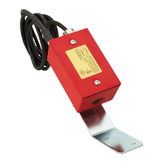
Special Purpose Supervisory Switch
Fig. RDPSP1
Important
This instruction manual contains important information about the
installation and operation of this supervisory switch. This manual
should be left with the owner/user of this equipment.
General Information
The unit is intended for supervision of non-rising stem gate valves
and other valves that cannot be monitored by conventional
supervisory switches. Turning the valve wheel will pull the plug out
of the jack and close a set of normally open contacts. A lockout will
prevent reinsertion and require removal of the cover. Tamperproof
screws are provided for the cover. Removal of cover, or cutting of
cord or ground faults will cause an open circuit. The device should
be wired to the trouble circuit of a fire alarm control panel.
Installation
1. Choose a location near the valve (safe from flooding) and
mount the bracket to the wall.
2. Rotate the box on the bracket until the plug faces the valve.
The plug must also point downward. Tighten the locknut on the
pivot.
3. Turn the valve to the full-open position. Insert the plug into the
jack. Tightly loop the 8-ft. waterproof cable through the valve
wheel and back into the box through the cable clamp. Close
valve to check that plug pulls out and then turn valve back to
full-open position. Cut the cord to the minimum length required
to make the connections within the box.
4. For all exterior applications, use 1/2" NPT, listed liquid-tight
conduit connectors.
5. Wire the device as per the circuit diagrams shown (see Figures
2-5). Trim the unused black wire flush with the cable casing and
cap the red wire of the cover tamper switch.
6. If a longer cable is required, use SJOW A 18-2, two conductor
18-gauge stranded rubber-jacketed cable.
7. Using the adhesive pad and wire tie provided, dress the wires
away from the lock-out mechanism.
8. When installing the cover, make sure the O-rings are in place on
the cover screws beneath the cover.
Warning
As stipulated by Factory Mutual and Underwriter's Laboratories, this
unit is not intended or designed for ordinary usage. It is a special
application device to be used for unusual conditions where no
other approved or listed method of protection is available or
practical, such as non-rising stem gate valves.
As this unit does not meet NFPA codes and standards (requiring
restoration of the signal when the valve is positioned to normal),
special attention should be given by the responsible parties to
assure that the proper operation of this device is maintained. This
device should only be restored to normal when the valve is in
normal condition.
IOM: 2.49
Issue A
05/04/2024
© 2024 Rapidrop
Rapidrop Global Ltd reserves the right to change the design, materials and specifications without notice to continue product development
Rapidrop Global Ltd
T: +44 (0) 1733 847 510 F: +44 (0) 1733 553 958
e: rapidrop@rapidrop.com
w: www.rapidrop.com
Specification
Dimensions (mm)
120 (215 with bracket) × 75 × 56
Dimensions (inch)
4¾ (8½ with bracket) × 3 × 2½
Shipping Weight
0.8 kg (1.7 lbs.)
Operating Temperature
-20ºC to 65ºC (-4ºF to 149ºF)
Range
Enclosure Rating
NEMA 3 UL Indoor/Outdoor Rated
2 wire, 18 gauge waterproof, 2.4 m long
Cable
(8 feet)
Operating Voltage
6/12/24V AC/DC
Maximum Operating
250 mA
Current
FM
Page 1 of 2
Advertisement

Related Manuals for Rapidrop RDPSP1

Summary of Contents for Rapidrop RDPSP1
- Page 1 T: +44 (0) 1733 847 510 F: +44 (0) 1733 553 958 Issue A 05/04/2024 e: rapidrop@rapidrop.com w: www.rapidrop.com Page 1 of 2 © 2024 Rapidrop Rapidrop Global Ltd reserves the right to change the design, materials and specifications without notice to continue product development...
- Page 2 T: +44 (0) 1733 847 510 F: +44 (0) 1733 553 958 Issue A 05/04/2024 e: rapidrop@rapidrop.com w: www.rapidrop.com Page 2 of 2 © 2024 Rapidrop Rapidrop Global Ltd reserves the right to change the design, materials and specifications without notice to continue product development...
Need help?
Do you have a question about the RDPSP1 and is the answer not in the manual?
Questions and answers