Table of Contents
Advertisement
Quick Links
Advertisement
Table of Contents

Summary of Contents for CoreTigo TigoGateway 1TE PROFINET
- Page 1 TigoGateway 1TE PROFINET ANUAL Revision 1.2 Jan 2024...
-
Page 2: Table Of Contents
3.2.3. LED Indications 3.2.4. Connection Points Installation Overview 4.1. Hardware Installation 4.1.1. Select the Mounting Location 4.1.2. Equipment Required 4.1.3. Mount the TigoGateway 4.1.4. Ground the TigoGateway 4.1.5. Demount the TigoGateway Page 2 of 77 Copyright © 2023 CoreTigo Ltd. - Page 3 8.2. IO-Link Diagnosis 8.2.1. Event Qualifier 8.2.2. IO-Link Wireless Master Event Codes 8.2.3. IO-Link Device Event Codes (Common) Technical Data 9.1. TigoGateway 1TE Specifications 9.2. Protocol Appendix A – Evaluation Agreement Page 3 of 77 Copyright © 2023 CoreTigo Ltd.
-
Page 4: List Of Figures
Figure 37: Path to TigoGatewayLEDsConfig ......................59 Figure 38: Configuration of QSI Threshold......................59 Figure 39: Status_LED_Event_Period ........................60 Figure 40: Configuration of Event Timeout......................60 Figure 41: Event Qualifier ............................67 Page 4 of 77 Copyright © 2023 CoreTigo Ltd. -
Page 5: List Of Tables
Table 32: Protocol Technical Data ........................72 Revision Control Author Name Description Rev. Date CoreTigo Original Document May 2023 CoreTigo Second version specific to TigoGateway Oct 2023 1TE model Updates – Regulations, images CoreTigo Jan 2024 Page 5 of 77 Copyright © 2023 CoreTigo Ltd. -
Page 6: Acronyms And Abbreviations
RSSI Received Signal Strength Indication System Management Standardized Master Interface SSlot Single Slot Software To be determined Vendor Specific W-Device Wireless Device (for example, TigoBridge) W-Master Wireless Master (for example, TigoGateway) Page 6 of 77 Copyright © 2023 CoreTigo Ltd. -
Page 7: Introduction
This symbol indicates a security notice which must be observed. Reference(s): This symbol indicates a cross-reference to other documentation. 1.5. Deviating Views The product views and illustrations in this User Manual may deviate from the actual product. Page 7 of 77 Copyright © 2023 CoreTigo Ltd. -
Page 8: Safety And Requirements
Evaluation of the safety of electrical systems and equipment. Warning: CoreTigo Ltd. does not assume any warranty or liability for damage caused to the product due to non-compliance with security measures or incorrect installation of the product. Page 8 of 77... -
Page 9: Power Drop For Write/Delete Access In File System
Contains FCC ID: 2ATSM-TGRFCM1. 2.7.3. ISED Warning CoreTigo Ltd. does not endorse any changes made to the device by the user of any kind. Any change or modification may void the user's right to use the device. -
Page 10: Wireless Notice
CAT5 - Ethernet Cable with RJ45 Connectors • PROFINET Supported PLC (not mandatory) Note: The abovementioned components are provided by CoreTigo Ltd. upon purchase. • PC or Notebook with a minimum of 1 additional Ethernet Port and Internet Access/PLC 2.8.2. Software... -
Page 11: Getting Started
(for example, CEL and UL), environmental signs (for example, disposal), and other data is provided in the form of side label attached to the device’s housing. For further details see Technical Data. Figure 1: Example of TigoGateway Side Label Page 11 of 77 Copyright © 2023 CoreTigo Ltd. -
Page 12: Network Topology
TigoGateway 1TE (PROFINET) User Manual 3.2.1. Network Topology The network topology in which the TigoGateway is used is described in the diagram below. Figure 2: TigoGateway Network Topology Page 12 of 77 Copyright © 2023 CoreTigo Ltd. -
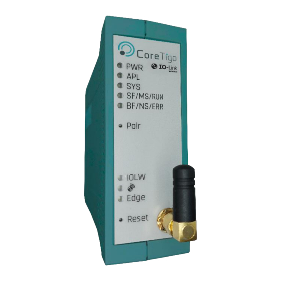
Page 13: Leds
5. BF/NS/ERR – Bus Failure 14. CH1 – RJ45 Ethernet Port 4 6. Pair/GEN - General 7. IOLW - IOLW Connected 8. QSI – Quality Signal Indicator 9. EDGE – Edge Operational Page 13 of 77 Copyright © 2023 CoreTigo Ltd. -
Page 14: Led Indications
(3 x Yellow, • 3 x Yellow "On" for 500 ms and "Off" for 500 ms 3 x Green) • 3 x Green "On" for 500 ms and "Off" for 500 ms Page 14 of 77 Copyright © 2023 CoreTigo Ltd. -
Page 15: Table 9: Tigogateway Device Status
One or more of the paired ports falls within the QSI threshold range, but none of them are below it. The paired ports are beyond the upper limit of the QSI threshold Page 15 of 77 Copyright © 2023 CoreTigo Ltd. -
Page 16: Figure 3: Bottom Panel
The LED turns on and off with a frequency of approximately 10 Hz to indicate high Ethernet activity: On for approximately 50 ms, followed by Off for 50 ms. The LED turns on and off in irregular intervals to indicate low Ethernet activity. Page 16 of 77 Copyright © 2023 CoreTigo Ltd. -
Page 17: Connection Points
8 IO-Link wireless devices. The types of data transferred (e.g. length and data type) may vary depending on the connected devices. Table 16: Top Panel Connectors Connector Location Dimensions Description SMA T1 Top Panel T1 Antenna (all variants of board) Page 17 of 77 Copyright © 2023 CoreTigo Ltd. -
Page 18: Table 17: Sma Antenna
Power Rating: 1 W Note: It is not permitted to use an alternative SMA antenna from the one supplied by CoreTigo Ltd. Using an alternative SMA antenna may result in a loss of device approval. Additionally, SMA antennas must be mounted for proper device functioning. -
Page 19: Installation Overview
It must have an unobstructed air supply Its cooling must not be impeded • Do not bridge any gaps with the unit to protect it from any tensile forces that may occur. Page 19 of 77 Copyright © 2023 CoreTigo Ltd. -
Page 20: Equipment Required
Via a cable lug and the mounting hole, if the TigoGateway is mounted on a non-conductive base. 2. Make sure that the contacts are attached solidly and that the cable cross-section is sufficient. Page 20 of 77 Copyright © 2023 CoreTigo Ltd. -
Page 21: Demount The Tigogateway
Connection Example with TigoBridge The connection example described below shows a typical installation that uses a TigoBridge to connect a wired IO-Link Device via a wireless connection to the IO-Link Wireless Master. Page 21 of 77 Copyright © 2023 CoreTigo Ltd. -
Page 22: Figure 5: Connection Example With Tigobridge
4. Connect the power cable (+24 V DC SELV or PELV) to the power connector of the W Bridge. 5. Switch on the power supply units of the TigoGateway and TigoBridge. Figure 5: Connection Example with TigoBridge Page 22 of 77 Copyright © 2023 CoreTigo Ltd. -
Page 23: Login To Tigogateway
1. Connect Ethernet cable to TigoGateway LAN1 port. Important: make sure Ethernet cable is connected to Network with DHCP capabilities as TigoGatway requires to get an IP from the network. 2. Use the URL provided by CoreTigo, which appears on the left side-label http://tigogateway-YYZZ:9001/ ,see Product Overview. -
Page 24: Built-In Software
(requires an MQTT broker on the third party software side) • Performance Monitoring: Packet Error Rate (PER) real-time display—enables analysis of latency and network interferences Link Quality Indication (LQI) Received Signal Strength Indication (RSSI) Page 24 of 77 Copyright © 2023 CoreTigo Ltd. -
Page 25: Linux Cockpit
It runs on demand only. Cockpit Usage Process 1. From the home page click the Get Started button in the Cockpit area of the page. 2. In the warning page which opens, click on Advanced. Page 25 of 77 Copyright © 2023 CoreTigo Ltd. - Page 26 TigoGateway 1TE (PROFINET) User Manual 3. Click on the Proceed to TigoGateway link. The Login window opens. 4. Enter the Username (tigogateway) and Password (tigogateway) provided to you by CoreTigo. 5. Click the green Log In button. The TigoGateway Cockpit dashboard opens.
- Page 27 8. To configure settings for these interfaces click on their names in the list. The details are displayed when you click on one of them. 9. Click the Automatic (DHCP) link listed alongside the item IPv4. Page 27 of 77 Copyright © 2023 CoreTigo Ltd.
- Page 28 10. Open the dropdown list available in Addresses. 11. Here you can fix a static IP Address through the Manual menu option which opens another window in which you can insert an appropriate IP address. Page 28 of 77 Copyright © 2023 CoreTigo Ltd.
-
Page 29: Docker
Docker: Accelerated, Containerized Application Development • Welcome - Portainer Documentation The Docker is used to promote a new business logic and upload it to a virtual application. Refer also to Docker Configuration. Page 29 of 77 Copyright © 2023 CoreTigo Ltd. - Page 30 TigoGateway 1TE (PROFINET) User Manual Docker Usage Process 1. From the home page click the Get Started button in the Docker area of the page. 2. In the warning page which opens, click on Advanced. Page 30 of 77 Copyright © 2023 CoreTigo Ltd.
- Page 31 TigoGateway 1TE (PROFINET) User Manual 3. Click on the Proceed to TigoGateway link. The Login window opens. 4. Enter the Username and Password provided to you by CoreTigo, and confirm the password. Page 31 of 77 Copyright © 2023 CoreTigo Ltd.
- Page 32 TigoGateway 1TE (PROFINET) User Manual The Quick Setup page opens. 5. Click the Get Started box (initial setup only) to access the Home page. This page is normally accessed from the side-panel menu, when required. Page 32 of 77 Copyright © 2023 CoreTigo Ltd.
- Page 33 TigoGateway 1TE (PROFINET) User Manual 6. Click the blue Docker icon.The Dashboard opens, displaying an overview of the product setup. Page 33 of 77 Copyright © 2023 CoreTigo Ltd.
-
Page 34: Configuration
Set all parameters for the TigoGateway, its connected IO-Link devices, and the MQTT Client in the TigoGateway. Monitor the TigoGateway and IO-Link devices in any system connected to TigoEngine. Page 34 of 77 Copyright © 2023 CoreTigo Ltd. -
Page 35: Configure Tigogateway
IO- configuration Controller, which in turn GSDML-V2.35- Defined by Applicable Applicable N/A tool) configures the TigoGateway. CoreTigo- the Linux TigoMaster- Cockpit PDCT- 20211202 TigoEngine TigoEngine Linux Cockpit Linux Cockpit Page 35 of 77 Copyright © 2023 CoreTigo Ltd. -
Page 36: Import The Gsdml File To The Profinet Io-Controller Software
4. In the Manage General Station Description Files window, make sure that the Installed GSDs tab is selected. 5. Click the ellipsis (…) button. Figure 9: Manage General Station Description Files - Installed GSDs Tab 6. Select the Source Path for the GSDML file. Page 36 of 77 Copyright © 2023 CoreTigo Ltd. -
Page 37: Figure 10: List Of Available Gsd Files
9. Click the Install button. When the installation is complete, a new module (TigoGateway) is added to the Hardware catalog under Other field devices. Figure 11: New Module Added to Hardware Catalog Page 37 of 77 Copyright © 2023 CoreTigo Ltd. -
Page 38: Configure The Ip Address
4. Click on the TigoGateway (which is outlined in Red) to open configuration fields. Figure 13: Device View 5. In the General tab, go to PROFINET interface [x3] > Ethernet addresses. 6. Under IP protocol, set the desired IP address. Page 38 of 77 Copyright © 2023 CoreTigo Ltd. -
Page 39: Configure Ports (Subslots)
Each port (subslot) needs configuring, as detailed in the rest of this section. Configuration port WP02 Configuration port WP03 Configuration port WP04 Configuration port WP05 Configuration port WP06 Configuration port WP07 Configuration port WP08 Page 39 of 77 Copyright © 2023 CoreTigo Ltd. -
Page 40: Figure 15: Device View Tab - Wireless Ports 1 Wp01-1 Wp08
2. In the Catalog pane, go to Submodules -> IOL wireless generic devices. Here you can see a list of the IO-Link wireless device types. For details of each device type see the table below. Figure 16: IO-Link Wireless Device Types Page 40 of 77 Copyright © 2023 CoreTigo Ltd. -
Page 41: Table 20: Io-Link Wireless Device Types
3. Configure each IO-Link wireless port (subslot). 4. Select the type of device that is / will be connected to the port being configured, and drag it into the port’s row in the Device View tab. Page 41 of 77 Copyright © 2023 CoreTigo Ltd. -
Page 42: Figure 17: Setting A Port's Device Type
Figure 17: Setting a Port’s Device Type A Device Inspector pane appears (outlined in in the image below). Figure 18: Device Inspector Pane 5. In the General tab (of the inspector pane) select Module Parameters. Page 42 of 77 Copyright © 2023 CoreTigo Ltd. -
Page 43: Figure 19: Module Parameters
7. Change the value of any other parameters as needed by the system: for details of the various parameters and their possible values, see Parameters. 8. Compile and download in order to apply the current settings. Page 43 of 77 Copyright © 2023 CoreTigo Ltd. -
Page 44: Figure 21: Show All Tags
10. In the Tags tab, set the W-Device tags. Figure 22: Tags Tab 11. In the Project Tree, under the relevant PLC go to Watch and Force Tables > Watch Table_1. Page 44 of 77 Copyright © 2023 CoreTigo Ltd. -
Page 45: Figure 23: Watch Table
TigoGateway 1TE (PROFINET) User Manual 12. In Watch Table_1, set the watch parameters. Figure 23: Watch Table 13. Use Watch Table_1 to monitor W-Device data for the TigoBridge, and for IO-Link Wireless sensors and actuators. Page 45 of 77 Copyright © 2023 CoreTigo Ltd. -
Page 46: Tigoengine Configuration
In order to use the TigoEngine it is necessary to have a valid user license. Licenses are granted by CoreTigo. Some are for a limited period with an expiry date, and some are perpetual. After expiration of the license the user will only be able to access the TigoEngine if the license has been renewed by CoreTigo. -
Page 47: Figure 25: Tigoengine Login Screen
• Password = admin 4. In TigoEngine’s Masters view, click the Connect New Master button. Figure 26: Connect New Master Button 5. In the Connect New Master window, set the following: Page 47 of 77 Copyright © 2023 CoreTigo Ltd. -
Page 48: Figure 27: Connect New Master
The OPC UA connection indication ( ) shows the OPC UA connection to the wireless master. When it is green, data exchange (process data & MQTT ) between the wireless master and TigoEngine is active. Page 48 of 77 Copyright © 2023 CoreTigo Ltd. -
Page 49: Docker Configuration
Portainer needs to be restarted. In this case, you should restart the TigoGateway device. 3. To create a new registry, select Registries in the side-panel menu. The Registries window opens. Page 49 of 77 Copyright © 2023 CoreTigo Ltd. - Page 50 TigoGateway 1TE (PROFINET) User Manual 4. Click the blue +Add Registry button. The Create Registry window opens. Page 50 of 77 Copyright © 2023 CoreTigo Ltd.
- Page 51 7. Select the stack or search for it. 8. Click the Remove button. The stack is removed. 9. The next step is to delete existing images (virtual applications). Select the image(s) in the side-panel menu. Page 51 of 77 Copyright © 2023 CoreTigo Ltd.
- Page 52 All images except the Portainer image should be selected. 10. Click Force Remove. The images are removed. 11. The next step is to create a new stack. Select Stacks in the side-panel menu. The Stacks List window opens. Page 52 of 77 Copyright © 2023 CoreTigo Ltd.
- Page 53 16. Under Actions, click the blue Deploy the Stack button. This process make take some time to complete. 17. After completion, check the Stacks > Containers list to verify the addition. Page 53 of 77 Copyright © 2023 CoreTigo Ltd.
-
Page 54: Commissioning
5. Use the MAC address or the device type, e.g. to identify the device. 6. Use the mouse pointer to select the corresponding device from the list of the devices found. 7. Click Configure > Set IP Address. Page 54 of 77 Copyright © 2023 CoreTigo Ltd. -
Page 55: Use An Opc Ua Client
For test purposes, you can use such a client as the UaExpert from Unified Automation GmbH (http://www.unifiedautomation.com). 6.2.1. Requirements • OPC UA client application installed on your local PC • A username and password that have Admin privileges • Device IP address Page 55 of 77 Copyright © 2023 CoreTigo Ltd. -
Page 56: Instructions
5. Under Authentication Settings, do the following: If you need write access, select the Username/Password option, and enter the relevant Username and Password (root/password) If read access only is sufficient, select the Anonymous option. Page 56 of 77 Copyright © 2023 CoreTigo Ltd. -
Page 57: Set The Device Date And Time Using Opc Ua
Inserting an example IP address into the formula gives the following: ((192 * 256 + 53) * 256 + 103) * 256 + 108 = 3224725356 The decimal number in this example IP address is 3224725356. Page 57 of 77 Copyright © 2023 CoreTigo Ltd. -
Page 58: Figure 33: Path To Ntpclientupdateconfiguration
2. Right-click NtpClientUpdateConfiguration, and then click Call. Figure 34: Right-Clicking NtpClientUpdateConfiguration 3. In the Call NtpClientUpdateConfiguration dialog box, set the following: ServerIpAddress = 3224725356 ServerIpAddressFallback = 3224725352 Figure 35: Call NtpClientUpdateConfiguration Dialog Box-Before Call 4. Click Call. Page 58 of 77 Copyright © 2023 CoreTigo Ltd. -
Page 59: Opc Ua Configuration For Leds Indications
The event timeout parameter determines the duration for which the IOLW LED indication remains yellow when a paired device sends an event and all ports are operational. To configure the Event Timeout parameter: 1. Navigate to the TigoGatewayLEDsConfig (Error! Reference source not found.) 2. Select Status_LED_Event_Period Page 59 of 77 Copyright © 2023 CoreTigo Ltd. -
Page 60: Figure 39: Status_Led_Event_Period
TigoGateway 1TE (PROFINET) User Manual Figure 39: Status_LED_Event_Period 3. Modify the value column associated with the Status_LED_Event_Period parameter to set the desired duration. (Units are in seconds) Figure 40: Configuration of Event Timeout Page 60 of 77 Copyright © 2023 CoreTigo Ltd. -
Page 61: Parameters
Enable process alarm 0: Disable PROFINET process alarms are (device notification) deactivated. 1: Enable PROFINET process alarms are activated. 0: PDCT Configuration source Configuration is done via a port and device configuration tool. Page 61 of 77 Copyright © 2023 CoreTigo Ltd. - Page 62 IO-Link device. 0 … 7 Slot Wireless slot number to be used for the port 0 … 2 Track Wireless track number to be used for the port Page 62 of 77 Copyright © 2023 CoreTigo Ltd.
-
Page 63: Table 23: Wireless Master Parameters
Table 23: Wireless Master Parameters Parameter Group Parameter Default Value Range Description 1 … 29 IO-Link Wireless Master ID Master identifier Master 0: disable The channel cannot be used by configuration the IO-Link Wireless Master Page 63 of 77 Copyright © 2023 CoreTigo Ltd. -
Page 64: Port Cycle Time
Time Base values (bits 6+7) and Multiplier values (bits 0-5), as shown in the following table. Table 24: Port Cycle Time Calculation Value Range Time Base Multiplier Resulting Cycle Time/Notes (Bits 6+7) (Bits 0-5) Free-running mode. Page 64 of 77 Copyright © 2023 CoreTigo Ltd. -
Page 65: I-Am-Alive Time
1 sec Time base is 1 sec 1 min Time base is 1 min 5 … 255 Reserved Reserved. Do not use. The multiplier has the value range of 1 … 255. Page 65 of 77 Copyright © 2023 CoreTigo Ltd. -
Page 66: Unique Id Parameters: Example
Byte 3 = C0 • Byte 4 = 30 • Byte 5 = 01 • Byte 6 = 00 • Byte 7 = 00 • Byte 8 = F3 • Byte 9 = 03 Page 66 of 77 Copyright © 2023 CoreTigo Ltd. -
Page 67: Status And Diagnostics
3: Event appears Bit 4–5 Type 0: Reserved 1: Notification 2: Warning 3: Error Bit 3 Source 0: Device (remote) 1: Master/Port Bit 0–2 Instance 0: Unknown 1–3: Reserved 4: Application 5–7: Reserved Page 67 of 77 Copyright © 2023 CoreTigo Ltd. -
Page 68: Io-Link Wireless Master Event Codes
Device temperature overrun Warning Clear source of heat 0x4220 Device temperature underrun Warning Insulate IO-Link Device 0x5000 Device hardware fault Error Exchange IO-Link Device 0x5010 Component malfunction Error Repair or exchange Page 68 of 77 Copyright © 2023 CoreTigo Ltd. - Page 69 See manual of the relevant 0x8DFF IO-Link Device 0xB000 – 0xB0FF Safety extensions See manual of the relevant IO-Link Device 0xB100 – 0xBFFF Profile-specific See manual of the relevant IO-Link Device Page 69 of 77 Copyright © 2023 CoreTigo Ltd.
- Page 70 See manual of the relevant (single shot) IO-Link Device 0xFFB9 Retry error Error See manual of the relevant IO-Link Device Any other code Reserved See manual of the relevant IO-Link Device Page 70 of 77 Copyright © 2023 CoreTigo Ltd.
-
Page 71: Technical Data
Certifications/ Compliance • ETSI EN 301489-1,17 • ETSI EN 300328 • EN 62479 • EN IEC 61326-1 • EN IEC 61000-3-2 • EN IEC 61000-3-3 EN 55032, 55035 Contains 2ATSM-TGRFCM1 UL 61010-1-2 Page 71 of 77 Copyright © 2023 CoreTigo Ltd. -
Page 72: Protocol
Synchronous with SYNCMAN Event: the application of the slave is synchronized to the SM2/3 Event Synchronous with SYNC Event: the application of the slave is synchronized to the SYNC0 or SYNC1 Event Page 72 of 77 Copyright © 2023 CoreTigo Ltd. - Page 73 No showing of Register Speed Counter Diff (0x0932:0x933) No MIO (PHY Management Interface) access from PROFINET Master side No physical Read-Write commands supported (APRW, FPRW, BRW) Reference to stack version V5.1 Page 73 of 77 Copyright © 2023 CoreTigo Ltd.
-
Page 74: Appendix A - Evaluation Agreement
CoreTigo and Company have agreed to the terms and conditions set forth hereunder: Product. As used herein “Product” shall mean CoreTigo’s proprietary product, as set forth in CoreTigo’s quotation attached hereto and/or associated and referencing this Agreement, including without limitation, any software or hardware components thereof, any user’s guides and/or technical manuals or other documentation... - Page 75 CoreTigo’s Confidential Information. It is further understood that use of Feedback, if any, may be made by CoreTigo at its sole discretion, and that CoreTigo in no way shall be obliged to make use of any kind of the Feedback or part thereof.
- Page 76 Agreement shall apply to all such third party software providers and third party software as if they were CoreTigo and the Product respectively. In addition, this Product contains open source components. Such open source components are protected under copyright law and are licensed to under specific license terms.
- Page 77 (ii) Company shall return or, at Company’s request, the Product and all of CoreTigo’s Confidential Information to CoreTigo and shall destroy all copies of the Product contained in any of its systems, and (iii) CoreTigo shall erase or otherwise destroy all copies of the Company’s Confidential Information, which was disclosed to CoreTigo under this Agreement.
Need help?
Do you have a question about the TigoGateway 1TE PROFINET and is the answer not in the manual?
Questions and answers