Table of Contents
Advertisement
Quick Links
Advertisement
Table of Contents

Related Manuals for Fastus UR-DS4AD

Summary of Contents for Fastus UR-DS4AD
- Page 1 IO-Link Hub *FASTUS is a product brand of OPTEX FA. UR-DS4AD UR-DS4DA User’s Manual For technical support and application assistance contact the Optex IO-Link experts at Ramco Innovations today! OPTEX FA CO., LTD. Ramco Innovations www.optex-ramco.com (800) 280-6933...
- Page 2 Introduction Thank you for purchasing the UR-DS4AD IO-Link IO-Link Hub, Analog I/O 4-input and UR-DS4DA IO-Link IO- Link Hub, Analog I/O 4-output. This manual includes the information required to use the UR-DS4AD and UR-DS4DA. Read this manual carefully before use, and fully understand the functions and performance before using UR- DS4AD/UR-DS4DA correctly.
-
Page 3: Table Of Contents
Connecting to the IO-Link communication terminals on the power terminal block ........11 Wiring to the analog input/output power supply .................. 12 Wiring to the device terminal block for UR-DS4AD ................12 Wiring to the device terminal block for UR-DS4DA ................13 ... - Page 4 Analog input specifications for UR-DS4AD ..................20 Analog output specifications for UR-DS4AD ..................21 Circuit Diagram ............................. 22 Analog input circuit diagram for UR-DS4AD ..................22 Analog output circuit diagram for UR-DS4DA ..................22 Process Data............................. 23 UR-DS4AD ............................
- Page 5 Ramco Innovations www.optex-ramco.com (800) 280-6933...
-
Page 6: Overview
1. Overview UR-DS4AD IO-Link Hub, Analog I/O 4-input UR-DS4AD is a remote analog input unit that specifies 4 analog input signals to control various actuators with process output data from the IO-Link master. It can be used to control devices with analog output, such as changing the speed of a motor, or adjusting flow rate or fan speed. -
Page 7: Dimensions
3. Dimensions UR-DS4AD (39.9) 21.5 Unit (mm) UR-DS4DA (39.9) 21.5 Unit (mm) Ramco Innovations www.optex-ramco.com (800) 280-6933... -
Page 8: Installation
3. Push the DIN rail mounting hook up to lock the product in place. DIN rail Push-in DIN rail mounting hook (This illustration is for UR-DS4AD) Install UR-DS4AD/UR-DS4DA at least 10 mm away from an adjacent device and structure. Ramco Innovations www.optex-ramco.com (800) 280-6933... -
Page 9: System Configuration
5. System Configuration Ramco Innovations www.optex-ramco.com (800) 280-6933... -
Page 10: Connection
Power supply for analog output devices Wiring to the device terminal block Connecting to the IO-Link communication terminals on for UR-DS4AD (See page12) the power terminal block(See page11) *Unit power (+24 V, 0 V) and C/Q are connected internally with the terminals of the e-CON socket. -
Page 11: Wiring To The Io-Link Master
Wiring to the IO-Link Master Connect the IO-Link master to either the e-CON socket on this product or the IO-Link communication terminals on the power terminal block. Connecting to the IO-Link communication e-CON socket. Applicable wires should be between AWG 28 to 20 stranded wires with a rated temperature of 75°C or higher. -
Page 12: Wiring To The Analog Input/Output Power Supply
For the wires to be used and recommended ferrule, refer to "Wire Installation" on page 13. Wiring to the device terminal block for UR-DS4AD Connect the wires for power supply and input signal of input devices to the 16-channel device terminal block. -
Page 13: Wiring To The Device Terminal Block For Ur-Ds4Da
• Device terminal block:(for UR-DS4DA) L+, M, A0 to 3, GND AWG28 to 16 Use wires with a temperature rating of 75 °C or higher. • Device terminal block:(for UR-DS4AD) V+, I+, GND, SLD AWG28 to 16 Use wires with a temperature rating of 75 °C or higher. -
Page 14: Recommended Ferrule And Crimping Tool
Recommended ferrule and crimping tool •Ferrule for the power terminal block The recommended ferrule is AI 0.5-10 WH (AWG20) from PHOENIX CONTACT. For dimensions and ferrules other than AWG20, refer to the table below. • Ferrule for the Device terminal block The recommended ferrule is AI 0.25-10 YE (AWG24) from PHOENIX CONTACT. -
Page 15: Wire Installation Method
Wire installation method 1. Press the open/close key (orange) of the wire insertion port Power terminal block for installation with a precision flathead screwdriver. 2. Insert the wire from the wire insertion port while pressing the open/close key. Insert the wire until the tip reaches the bottom. -
Page 16: Wire Removal
Wire Removal 1. Press the open/close key (orange) of the wire insertion port Power terminal block to be removed with a precision flathead screwdriver. 2. Pull out the wire while holding down the open/close key. * If the ferrule is stuck inside the terminal block and cannot be removed, the terminal block may be damaged by forceful removal. -
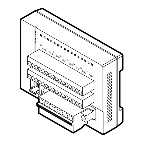
Page 17: Part Names
7. Part names UR-DS4AD Name Function POWER LED (green) Lights up when power is turned on for the analog input device. Illuminated : After startup, before IO-Link communication is established 1 second on 0.1 second off : IO-Link communication established COM LED (green) 0.55 second on 0.55 second off : Find me 0.1 second on 0.1 second off... -
Page 18: Ur-Ds4Da
UR-DS4DA Name Function POWER LED (green) Lights up when power is turned on for the analog output device. Illuminated : After startup, before IO-Link communication is established 1 second on 0.1 second off : IO-Link communication established COM LED (green) 0.55 second on 0.55 second off : Find me 0.1 second on 0.1 second off : IO-Link communication cutoff... -
Page 19: Specifications
Device terminal block: AWG 28 to 16 Material Unit: PC; DIN rail mounting hook: POM; Terminal block: PA UR-DS4AD:Approx. 105 g (including terminal blocks, when not wired) Weight UR-DS4DA:Approx. 95 g (including terminal blocks, when not wired) Instruction manual, Device terminal block (UR-DS4AD:two pieces, UR-DS4DA:one... -
Page 20: Io-Link Specifications
0.7 ms IO-Link revision Communication speed COM3 (230.4 kbps) Communication function operation power supply IO-Link power supply Analog input specifications for UR-DS4AD Item Specifications Number of Input channels 4 CH Type of analog input Voltage (0 to 10 V, -10 to 10 V, 0 to 5 V, 1 to 5 V)/Current (0 to 20 mA,... -
Page 21: Analog Output Specifications For Ur-Ds4Ad
Analog output specifications for UR-DS4AD Item Specifications Number of output channels 4 CH Type of analog output Voltage (0 to 10 V, -10 to 10 V, 0 to 5 V)/ Current (0 to 20 mA) switchable for all channels... -
Page 22: Circuit Diagram
9. Circuit Diagram Analog input circuit diagram for UR-DS4AD 168.3 K ohm V: +0 to 3 82 ohm 82 K ohm I :+0 to 3 Internal circuit − Analog output circuit diagram for UR-DS4DA Voltage sensing 15 ohm −... -
Page 23: Process Data
The process data exchanged by the product with the IO-Link master using IO-Link cyclic communication is as follows. UR-DS4AD IO-Link process data is transferred in big endian format. The table below is also in big endian format. The IO-Link master UR series from OPTEX FA transfers IO-Link process data converted into little endian format to the host network by default, so please refer to the table below for "Word assignment"... -
Page 24: Word Assignment
Word assignment Example: When using the IO-Link master UR series of OPTEX FA (default setting: little endian) <Overview> Byte Process Word data Upper Upper Process input n+6 Process input n+7 Process input n+4 Process input n+5 Process input data Process input n+2 Process input n+3 Process input n+0 Process input n+1... -
Page 25: Ur-Ds4Da
UR-DS4DA IO-Link process data is transferred in big endian format. The table below is also in big endian format. The IO-Link master UR series from OPTEX FA transfers IO-Link process data converted into little endian format to the host network by default, so please refer to the table below for "Word assignment" (page 25). Byte Process data bit 7... - Page 26 <Detail> Process Byte Word data 15 Channel 0 Analog output upper byte Channel 0 Analog output lower byte Channel 1 Analog output upper byte Channel 1 Analog output lower byte Process Channel 2 Analog output upper byte Channel 2 Analog output lower byte output data Channel 3 Analog output upper byte Channel 3 Analog output lower byte...
-
Page 27: Service Data
11. Service Data The service data for UR-DS4AD/UR-DS4DA that can be read and written via IO-Link ISDU handling is as follows. UR-DS4AD System Initialization of setting value command Stops IO-Link communication after reverting setting values to default values (Back-to-Box) Device lock Unlocks the storage function. - Page 28 Averaging time Sets the averaging time for channels 0 to 3. ✓ 750 µs 1 to 4 ✓ 1.5 ms 3 ms 6 ms 12 ms 24 ms 48 ms Internal -2739 to Returns the temperature on the internal board. The unit is 0.1°C. temperature 10461 Operating time...
-
Page 29: Ur-Ds4Da
UR-DS4DA Initialization of setting value System command Stops IO-Link communication after reverting setting values to default values (Back-to-Box) Unlocks the storage function. Device lock ✓ Storage function lock. Can be used to set a name for this unit, such as the device Tag name ✓... - Page 30 Specifies the decimal point position for the process output data Displayed displayed on the IO-Link Master UR series display. The first ✓ decimal point byte corresponds to channel 0. position Each channel is set separately. Subindex number 1 1 to 4 0 to10 ✓...
-
Page 31: Events
12. Events Events occurring in UR-DS4AD/UR-DS4DA. Event code Message Details 0x4210 Temperature range has This occurs when the temperature on the circuit board been exceeded exceeds 85°C. Generated every 10 minutes. Immediately lower the ambient temperature. 0x1800 Minimum span value is... -
Page 32: Troubleshooting
13. Troubleshooting How to handle UR-DS4AD/UR-DS4DA when it does not work properly or when problems occur. ■Common for UR-DS4AD/UR-DS4DA Symptom Checkpoints and countermeasures POWER LED does not light up Check that voltage is applied to the Unit power’s 24 V and 0 V and the I/O power’s L+ and M. - Page 33 Check that the analog output setting (voltage/current range) of the analog output device matches the input setting of the UR-DS4AD. Check that the bit corresponding to the input range setting of the process output data of the UR-DS4AD is set correctly.
- Page 34 Symptom Checkpoints and countermeasures Noise on the analog input Select a current-output device because the impedance of the receiving equipment is lower with a current input than with a voltage input, making it more resistant to noise. Use shielded wires with GND on the braided wire side for the analog inputs (0 to 3 for V+ and 0 to 3 for I+) and connect these shields to the SLD terminals.
- Page 35 Symptom Checkpoints and countermeasures Output range LED does not light up Check that the IO-Link master to which the UR-DS4DA is connected is connected to the field network. Change the output range setting to a fixed value (0 to 10V, 0 to 20mA, etc.) The output range LED lights up This behavior occurs during resetting of the internal microcontroller...
- Page 36 UR-DS4_UM-E_001_2402 The information in this user’s manual is correct as of February 2024 Ramco Innovations www.optex-ramco.com (800) 280-6933...
Need help?
Do you have a question about the UR-DS4AD and is the answer not in the manual?
Questions and answers