
Subscribe to Our Youtube Channel
Summary of Contents for RefPlus ONS
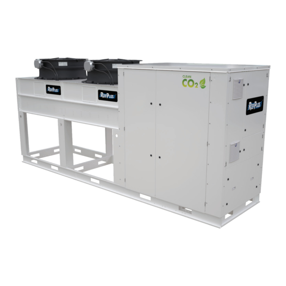
- Page 1 CONDENSING UNIT INSTALLATION, OPERATION AND MAINTENANCE MANUAL AIR-COOLED - VERTICAL DISCHARGE CO TRANSCRITICAL CONDENSING UNIT...
-
Page 3: Table Of Contents
TABLE OF CONTENTS 1. SAFETY CONSIDERATIONS ...................... 2. INTRODUCTION .......................... 3. PRODUCT DESCRIPTION ......................4. MAIN COMPONENTS ......................... 5. HANDLING AND RIGGING ......................6. INSTALLATION ..........................6.1 COMPLETE PRE-INSTALLATION INSPECTION ....................8 6.2 INSTALLATION LOCATION ............................ 8 6.3 UNIT WIRING ................................10 6.4 REFRIGERATION PIPING ............................ -
Page 4: Safety Considerations
INTRODUCTION 1. SAFETY CONSIDERATIONS 2. INTRODUCTION Installing, starting up, and servicing equipment can be These instructions describe the installation, start-up and hazardous due to system pressures, electrical components service of an outdoor, air-cooled CO condensing unit and equipment location (roofs, elevated structures, etc.). with one or several semi-hermetic compressors for high, Only trained and qualified installers as well as service medium or low temperature applications. -
Page 5: Main Components
MAIN COMPONENTS 4. MAIN COMPONENTS - MEDIUM & HIGH TEMP. COPELAND OR BITZER COMPRESSOR SUPERHEAT PLATE HEAT EXCHANGER MAWP: 1885 PSIG/130 BAR HEAT RECLAIM (OPTION) HIGH-PRESSURE CO FLASH TANK PLATE HEAT EXCHANGER (RECEIVER) MAWP: 1885 PSIG/130 BAR MAWP:1305 PSIG/90 BAR OIL SEPARATOR/RESERVOIR COALESENT OIL SEPARATOR WITH INTERGRATED RESERVOIR... - Page 6 MAIN COMPONENTS 4. MAIN COMPONENTS - LOW TEMP. 2-STAGE DORIN COMPRESSOR HIGH-PRESSURE CO FLASH TANK (RECEIVER) MAWP:1305 PSIG/90 BAR OIL SEPARATOR/RESERVOIR COALESENT OIL RESERVOIR AND OIL SEPARATOR COMBINED 98.5% SEPARATION EFFICIENCY. MAWP: 2030 PSIG/140 BAR STAINLESS STEEL DISCHARGE LINE NO FITTINGS TO PREVENT UNWANTED LEAKS AND SUBCOOLING/SUPERHEATING LONG RADIUS TO PREVENT...
-
Page 7: Handling And Rigging
HANDLING AND RIGGING 5. HANDLING AND RIGGING Fork Lift – Do not use fork lifts against sheet metal panels or coils. The compressor side of the condensing unit is the Good handling and rigging practices must be followed heaviest and should be facing the lift truck. Make sure forks to protect units from damage. -
Page 8: Installation
INSTALLATION 6. INSTALLATION If condensing units are mounted on the ground, adequate protection must be provided to avoid damages. A levelled 6.1 COMPLETE PRE-INSTALLATION INSPECTION concrete base, at least 6 inches (152 mm) above ground must be provided to protect against ground water. It will Check all items against the bill of lading to make sure also help keep the gas cooler coil clean from grass, dirt and all crates and boxes have been received. - Page 9 INSTALLATION FENCE AIR FLOW MIN. MIN. MIN. AIR FLOW 12” W = total width of unit W = total width of unit (includes double row units) (includes double row units) Figure 2 Proper mounting arrangement - distance to wall Figure 4 Proper mounting arrangement AIR FLOW AIR FLOW MIN.
-
Page 10: Unit Wiring
INSTALLATION 6.3 UNIT WIRING IMPORTANT: Wire connections may have come loose during transit. Check all screws for tightness prior to starting up the unit. The unit must be grounded. GASKET SUPPORT All system wiring must follow applicable local and national codes. Internal wiring of fan motors, compressors, controllers, sensors and contactors have been completed at the factory. -
Page 11: Line Sizing And Basic Piping Rules
INSTALLATION 6.5 LINE SIZING AND BASIC PIPING RULES BASIC PIPING RULES: 1. Ensure proper liquid refrigerant feed to evaporators. LINE SIZING: 2. Provide practical refrigerant line sizes without excessive For proper line sizing, use an industry accepted program pressure drop. from a refrigerant or refrigeration valve manufacturer. - Page 12 INSTALLATION INSTALL EXPANDER IN HORIZONTAL PIPE SLOPE 1/4” PER 10 FT. TOWARD COMPRESSOR INSTALL REDUCERS IN VERTICAL PIPE IMPROPER PROPER PROPER Figure 8 Suction oil trap construction SUCTION LINE SUCTION LINE TO COMPRESSOR TO COMPRESSOR EVAP. EVAP. RED TEE RED TEE STR.
- Page 13 INSTALLATION DOUBLE RISER WHEN DOUBLE RISER NECESSARY WHEN NECESSARY MULTIPLE EVAPORATORS MULTIPLE EVAPORATORS MULTIPLE EVAPORATORS ON MULTIPLE EVAPORATORS ON STACKED ON SAME LEVEL: ON DIFFERENT LEVELS: SAME LEVEL: COMPRESSOR SAME LEVEL: COMPRESSOR COMPRESSOR ABOVE COMPRESSOR ABOVE BELOW ABOVE (ARRANGEMENT PREFERRED) Figure 10 Multiple evaporator suction line construction MUST RISE ABOVE HEIGHT OF EVAPORATOR...
-
Page 14: Liquid Line
CAREL PRack pR300T controller which is standard on all expansion valve manufacturer rating when selecting the models. This controller has an integrated driver board to valve. Use EEV that matches the RefPlus condensing unit control two CO electronic valves (HPV & BPV). -
Page 15: High Pressure Electronic Valve (Hpv)
PRINCIPLES OF OPERATION It has a total of 12 analogue inputs (AIs) for pressure 7.4 BYPASS LINE ELECTRONIC VALVE (BPV) and temperature sensors, 4 analogue outputs (AOs) with (MEDIUM/HIGH-TEMPERATURE UNITS ONLY) 0/10VDC signal for modulating devices, 12 digital inputs Medium and high-temperature units are equipped with (DIs) for switches and alarms, and 13 digital outputs either a CAREL E*V series or Parker GC/FGB series high- (DOs) for commands and activations. -
Page 16: Gas Cooler: Coil
PRINCIPLES OF OPERATION 7.6 GAS COOLER: COIL Tanks with less than 10 ft volume come standard with one pressure relief valve. Larger tanks come with dual relief Gas cooler coil is designed and manufactured in accordance valves and changeover valves. Dual relief valves are also with cETLus requirements with 1741 psig/120 barg MAWP. -
Page 17: Mechanical High Pressure Safety Switch
In single-evaporator applications, this controller stops the condensing unit when the evaporator is in defrost mode. For more information about the Guardian+ RC-S controller, please refer to its manual, available at refplus.com. Figure 17 Mechanical high-pressure safety switch... -
Page 18: Controls And Operation
If any additional • Date and time modifications are needed, please contact RefPlus technical • Suction, gas cooler, and flash tank pressures as well as support team. gas cooler outlet temperature The interface is made up of a screen and six buttons as •... - Page 19 CONTROLS AND OPERATION SYSTEM ON/OFF Compressor config. a.f. Configuration The system should ALWAYS be ON through the software a.g. Advanced Advanced adjustment in the following screen. In the program, it is set to switch the unit ON if a signal (digital input) is received from an a.g.
-
Page 20: Standard Sequence Of Operation
If a need arises for changing the transcritical temperature (LT) applications, the default setpoint is 200.2 parameters, please contact the RefPlus technical team. psig/13.8 barg, with an adjustment limit range of 163.1 to 220.8 psig (11.2 to 15.2 barg). -
Page 21: Optional Evaporator Defrost
For more information regarding RefPlus' Opti-Mist+ 8.3 OPTIONAL EVAPORATOR DEFROST Adiabatic System, please visit Refplus.com or contact a The defrost sequence with this CO system is completely RefPlus representative. controlled and managed by the Guardian+ RC-S evaporator NOTE: In cases where several condensing units are controllers. -
Page 22: Oil Change After Initial Start-Up
START-UP • Then go to input/output menu. After proper vacuum is achieved and maintained, break the system vacuum only with gas CO . Never break vacuum • Then go to Manual Management menu. with liquid CO • Then go to vacuum menu and activate vacuum mode. With triple point of 60 psig/-69.8 F (4.2 barg/-56.6 C), if... -
Page 23: Service
SERVICE 10. SERVICE System operating temperature, oil level, system suction pressure, and gas cooler pressure should be checked and recorded periodically to ensure stable system operation. For any help, tips, and questions pertaining to the condensing unit, refer to the troubleshooting chart on page 25 . IMPORTANT: Disconnect all power before servicing. -
Page 24: Oil In Semi-Hermetic Compressors
Verify the required amount of oil in the compressors. Some Serious Manual switch ID additional oil may be required when excessive refrigerant charge is required. Contact RefPlus for more details. Common fan overload Serious Manual POE oil must be used with all our CO condensing units. -
Page 25: Troubleshooting Chart
TROUBLESHOOTING 11. TROUBLESHOOTING CHART PROBLEM POSSIBLE CAUSES POSSIBLE CORRECTIVE STEPS 1. Main switch open. 1. Close switch 2. Fuse blown. 2. Check electrical circuits and motor winding for shots or grounds. Investigate for possible overloading. Replace fuses after fault is corrected. 3. - Page 26 TROUBLESHOOTING PROBLEM POSSIBLE CAUSES POSSIBLE CORRECTIVE STEPS 1. Lack of refrigerant. 1. Check for leaks. Repair leak and add charge. 2. Evaporator dirty or iced. 2. Clean evaporator. Verify the defrost settings and operation 3. Clogged suction line or compressor 3.
-
Page 27: Replacement Parts
2. Discharge valve partially shut. 2. Open valve. 3. Blown valve plate gasket. 3. Replace gasket. Compressor thermal protector switch 4. Dirty gas cooler coil. 4. Clean coil. open 5. Overcharged system. 5. Reduce charge. REPLACEMENT PARTS Download the parts manual at http://refplus.com/en/parts-services/... -
Page 28: Startup Report Form
STARTUP REPORT FORM CONDENSING UNIT STARTUP REPORT FORM IMPORTANT: This startup report form must be filled out, signed and sent to RefPlus for the warranty to be honoured. 1. GENERAL INFORMATION JOB LOCATION: ____________________________________________________________________________________________________________________________________ REFPLUS RJ No: CONTRACTOR NAME: CONDENSING UNIT MODEL No.: CONDENSING UNIT SERIAL No.:... - Page 29 _____________ _____________ _____________ _____________ _____________ _____________ DISCHARGE (PSIG) EVACUATION: FINAL MICRON _____________ _____________ _____________ _____________ _____________ _____________ NUMBER TIMES 4. FIELD INSTALLED EXPANSION VALVE MANUFACTURER MODEL DATE: TECHNICIAN: SIGNATURE: FILL OUT FORM MANUALLY, TAKE A PHOTO AND SEND TO: service@refplus.com...
-
Page 30: General Warranty
GENERAL WARRANTY REFPLUS (SELLER) WARRANTS THAT THE EQUIPMENT MANUFACTURED BY THE SELLER, INCLUDING SERVICE PARTS, AND SOLD UNDER THIS CONTRACT SHALL BE FREE FROM DEFECTS IN MATERIAL AND WORKMANSHIP FOR A PERIOD OF TWELVE (12) MONTHS FROM THE DATE OF EQUIPMENT START-UP OR EIGHTEEN (18) MONTHS FROM THE DATE OF SHIPMENT, WHICHEVER OCCURS FIRST. - Page 31 NOTES __________________________________________________________________________________________ __________________________________________________________________________________________ __________________________________________________________________________________________ _________________________________________________________________________________________ _________________________________________________________________________________________ __________________________________________________________________________________________ __________________________________________________________________________________________ __________________________________________________________________________________________ __________________________________________________________________________________________ __________________________________________________________________________________________ __________________________________________________________________________________________ __________________________________________________________________________________________ __________________________________________________________________________________________ __________________________________________________________________________________________ __________________________________________________________________________________________ __________________________________________________________________________________________ __________________________________________________________________________________________ __________________________________________________________________________________________ __________________________________________________________________________________________ __________________________________________________________________________________________ __________________________________________________________________________________________ __________________________________________________________________________________________ __________________________________________________________________________________________ __________________________________________________________________________________________ __________________________________________________________________________________________ __________________________________________________________________________________________ __________________________________________________________________________________________ __________________________________________________________________________________________ __________________________________________________________________________________________ __________________________________________________________________________________________ __________________________________________________________________________________________ __________________________________________________________________________________________ __________________________________________________________________________________________ __________________________________________________________________________________________ __________________________________________________________________________________________ __________________________________________________________________________________________ __________________________________________________________________________________________ __________________________________________________________________________________________ __________________________________________________________________________________________ __________________________________________________________________________________________ __________________________________________________________________________________________ __________________________________________________________________________________________...
- Page 32 CERTIFIED ISO-9001 PENDING IOM_CU CO2_EN-R0 RefPlus Inc. reserves the right to make any changes in the design or USA & CANADA 1-888-816-2665 / refplus.com specifications of any product at any time without notice. 2777 Grande-Allée, Saint-Hubert, Québec, Canada, J4T 2R4 ©...
Need help?
Do you have a question about the ONS and is the answer not in the manual?
Questions and answers