
Summary of Contents for Adele Aero AdeleX-10
- Page 1 Adele Aero VTOL AdeleX-10 Small-sized FPV carrier Assembly and Operation Manual AAX10.000.000 Revision 1.1 dated April 21, 2024...
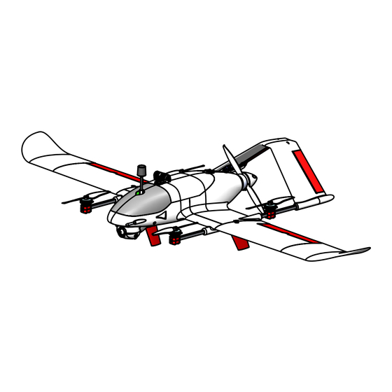
- Page 2 The aircraft is capable of taking off and landing vertically on unprepared and limited-size platforms and at the same time flying quickly in horizontal flight. In airplane mode, AdeleX-10 consumes approximately three times less energy than when hovering. Main characteristics:...
-
Page 3: Assembly Recommendations
Assembly recommendations Security measures: Work with glue and activator in a well-ventilated area. Do not leave parts or the assembled aircraft in direct sunlight or in rooms with temperatures above 40 degrees for a long time without cooling. Observe polarity when connecting power sources and various equipment. -
Page 4: Printing Options
Printing options To achieve the best results, we strongly recommend following the instructions. The model is designed for a printing area of 220x220x200 mm Structurally, the model parts are divided into two types, for each You need to configure your print profile: Parts made of thin-walled ABS (PLA+, PETG), body, stabilizer and wings. - Page 5 List of Printed Parts Parts marked as “mirror” will be reflected in the slicer according to quantity. The total weight of all parts is approximately 370 grams.
- Page 6 Parts location on the printer's bed An example of the location and orientation of parts. Supports must be turned off.
- Page 7 Parts location on the printer's bed An example of the location and orientation of parts. Supports must be turned off.
- Page 8 Parts location on the printer's bed An example of the location and orientation of parts. Supports included only on parts AAX10.003.Stabilizer To eliminate the generation of unnecessary structures from above, enable the "support blocker" modifier...
- Page 9 Parts location on the printer's bed An example of the location and orientation of parts. Supports must be turned off.
- Page 10 General view of the model Basic assembly units in the archive with the files are located in separate folders Right wing Motormont frame Stabilizer AAX10.002.Console-1 MFS.Motormount19 AAX10.003.Stabilizer Cover AAX10.100.Mainhatch Left wing AAX10.002.Console Servo Pan&Tilt Fuselage MFS.DJIGimbal AAX10.001.Fuselage...
- Page 11 Stabilizer AAX10.003.Elevatorshaft (1) Wire parts Insert until stop Scale 1:1 AAX10.003.Elevator AAX10.003.Stabilizer Screws М2.2.х10 Hardware Self-tapping screws: Rod end 2.2x9,5 - 4 pcs nylon 1.2 mm Hardware included with servo AAX10.003.Elevatorrod (2) Do not tighten the screws Servo Gh-s37d before installation on beams...
- Page 12 Wing Right and left consoles are mirrored AAX10.002.C2 Locking nut M3 Press in AAX10.002.C1 AAX10.002.Knob Bolt M3x16 Press in AAX10.002.Aileron AAX10.002.Aileronshaft (1) Insert all the way into the hole Wire parts using some thin tool Scale 1:1 Screws 2,2x16 Hardware included with servo Rod end nylon 1.2 mm...
-
Page 13: Main Hatch
Main hatch Bolt М3х16 AAX10.002.Knob Bolt М5х25 MFS.Gopromount MFS.Gopromountknob Lock nut M3 Press in Bolt М5х25 AAX10.001.Mainhatch2 AAX10.001.Mainhatch1 Screws 2.2х9.5 Harware Self-tapping screws: 2.2х9,5 - 2 pcs Bolts: М3х16 - 1 pcs М5х25 - 1 pcs Nuts: M3 lock nut - 1 pc. M5 lock nut - 1 pc. - Page 14 Thrust motor prop and FC stack Lock nut М5 MFS.Motormount19 Standard motor mounting, M3x8 screws Screws М2,2х9,5 Motor 2807 1300 kv ESC 30A Propeller 7042 Connector ХТ30 Hardware: (option) Screws М2,2х9,5 2 pcs FC SpeedyBeeF405 stack (option) Attach the GPS module to double-sided foam tape FC SpeedyBee F405...
- Page 15 Pan&tilt 1 DJI Vista option Snap in GH-s37d the lens protection (EMax Es9051) Camera Caddx Polar (Nebula) Servo Use standard screws standard hardware to adjust the camera position М2,2х6,5 Fixes the servo rocker in the niche 2x8 Camera rotation axis Insert Do not tighten! the antenna...
-
Page 16: Pan And Tilt
Pan&tilt 2 When assembling the gimbal, place the servos in such a way that the working stroke of the servos corresponds to the working stroke of the gimbal. All gimbal control channels must be in neutral position (1500 µs) before tuning. - Page 17 Fuselage 1 Servo extension 200 mm. Insert according to the mark above Screws Square profile carbon 2,2х9,5 6х6х410 mm Do not tighten too much AAX10.001.Latch Screws 2.2х16 screwing F1 and F2 Hardware Self-tapping screws: 2,2х9,5 - 13 pcs 2.2х16 - 4 pcs Screws 2,2х9,5 Screws 2.2x9.5 for clamping beams.
- Page 18 Fuselage 2 Screws Screws Propeller 2,2х6,5 AAX10.001.Gauge17 М2х8 Gemfan 5126-2 Airspeed sensor Matek ASP-4245 AAX10.001.Gauge70 AAX10.001.Motormount Motor EMax 2004 1600 kv Screw 2,2х9,5 Screws secure the pitot tube М2х16 Hardware Pitot tube Matek Self-tapping screws: 2,2х6,5 - 2 pcs Use templates to install lifting 2,2х9,5 - 1 pc motors correctly.
- Page 19 Fuselage 3 Connect to FC FC stack Screw М3х8 Screw 2.2x9.5 using 200mm servo fixing the motormount Push the stack into extensions (from the motor the rails and secure and 28 AWG wires standart harware) (camera, servo and fan) Screws 2,2х9,5 for pan&tilt installation С...
- Page 20 Fuselage 4 Secure the wires from the After installing the stabilizer, motors with ties to the arms make sure that the lift screws do not touch anything, including the pushing propeller Push the stabilizer until stop Tighten the screws on both Holes for cable ties sides after installing the stabilizer...
- Page 21 General assembly Cover Battery strap Battery 6s1p 21700 Spar carbon square profile 6x6x500 mm Insert the aileron servo cable into the mating part in the center section, observing the polarity ATTENTION! FOR ALL CHECKS OF ELECTRONICS INDOORS, DUE TO ONBOARD BATTERY CONNECTION, ALL PROPELLERS After installing the console on MUST BE REMOVED FROM THE MOTORS TO AVOID SERIOUS the spar and connecting the...
- Page 22 Views of the model...
- Page 23 Battery consumption planning A VTOL aircraft, being a hybrid of a quadcopter and an airplane, has some power supply features, unlike classic airplanes and copters. When planning a flight, it is necessary to take into account that VTOL aircraft consume the battery differently during takeoff, landing, hovering and cruising flight (see information) It is recommended to choose open spaces without houses or power lines for...
- Page 24 Pre-flight preparation 1 ATTENTION! Avoid excessive efforts when assembling the airplane to avoid damaging it! Remove the battery Install the freshly charged battery, compartment cover by carefully securing it with a belt. turning the latch 90 degrees If necessary, move the battery to correct alignment.
-
Page 25: Pre-Flight Preparation
Pre-flight preparation 2 CG marks Check the location of the center of gravity (CG): To do this, you need to place your index fingers on special marks on the bottom of the wing and hang the plane horizontally. ACCEPTABLE CG markes UNACCEPTABLE CORRECT ATTENTION! Checking the location of the center of gravity is... - Page 26 Pre-flight preparation 3 Inspect the holes It is necessary to carefully blow Remove the plug from the airspeed from a distance of 20-30 cm sensor tube (Pitot) 14. towards the tube and make sure Make sure that the tube holes are that the air speed changes its value clean and that the speed readings on to more than 5 m/s.
- Page 27 Takeoff Check the goggles' OSD to ensure that the aircraft has reliably determined its location. 1 minute after connecting the power, the number of satellites should be 3-7. For the best result (more than 10 satellites), you can wait another 3-5 minutes for the almanac to be updated inside the GPS receiver. If GPS is not available, it is possible to fly without receiving the launch coordinates.
- Page 28 Flight The flight along the route is carried out as standard for airplanes. If there is a GPS signal, the current coordinates will be displayed on the OSD, in addition, the arrow will point to the starting point. Cruising flight speed: 65-75 km/h. At this speed there will be minimal battery consumption.
- Page 29 Landing ATTENTION! In case of loss of orientation and/or control of the device, it is necessary to immediately move all (except arm switch) toggle switches to their neutral position (away from you), set the throttle stick to the central position, the QHOVER mode will turn on, then take all measures to return the aircraft or for an emergency landing .
- Page 30 Post-flight preparation 1 Disconnect and Open the battery remove the compartment cover. battery. Inspect Inspect the antenna Inspect control surfaces, propellers and housing parts for damage Inspect pitot tube holes Clean up the camera lens Inspect the aircraft for damage. Clean from dust, dirt and other deposits.
- Page 31 Post-flight preparation 2 Unscrew the knob After disconnecting the aileron wires, remove the consoles and pull out the spar The right wing is Disconnect the aileron removing in the same servo cable way as the left one.
-
Page 32: Maintenance
Maintenance AdeleX-10 does not require time-consuming special maintenance. It is only necessary to inspect the device every time during pre-flight and post- flight preparations for damage. Pay special attention to the propellers, control surfaces, the pitot tube and the camera.
Need help?
Do you have a question about the AdeleX-10 and is the answer not in the manual?
Questions and answers