Table of Contents
Advertisement
Quick Links
Advertisement
Table of Contents

Summary of Contents for GreenPower Master 60
- Page 1 AIR TO WATER HEAT PUMP USER & INSTALLATION MANUAL Models : Master 60 / 90 / 120 / 160 / 180 / 180 TRI / 260 TRI IMPORTANT NOTE: Thank you very much for purchasing our product. Before using your unit,...
-
Page 2: Table Of Contents
Contents list 1 GENERAL ................................- 2 - 2 Safety warnings ..............................- 2 - 2.1 Usage and installation warnings ......................- 2 - 2.2 Personal safety warnings ........................- 3 - 2.3 Transport, storage and handling warnings ...................- 4 - 2.4 Freeze protection warnings ........................- 4 - 3 SYSTEM DESCRIPTION ........................... -
Page 3: General
1 GENERAL Thank you for choosing a Master series heat pump. This is a heat pump capable of providing the ideal level of comfort for your home, always with a suitable hydraulic installation. The unit is an air source heat pump for space heating/cooling and sanitary water heater for houses, apartment blocks and small industrial premises. -
Page 4: Personal Safety Warnings
designed. Any other use is considered unsuitable and therefore hazardous. The manufacturer shall not be considered liable under any circumstances for damage caused by unsuitable, erroneous or irrational use. Remove all the packaging and check the contents are complete. In case of doubt, do not use the heat pump. -
Page 5: Transport, Storage And Handling Warnings
2.3 Transport, storage and handling warnings The heat pump must be transported, handled and stored vertically. Tipping the machine may cause the compressor or other components damage. Do not twist, loosen or pull the external electric cables of the heat pump. Do not insert any sharp objects through the fan grille or into the fan itself. -
Page 6: System Description
and on alert, the heat pump must be connected to the mains and have a power supply, even if it is switched off or not in use. A water filter should be installed in the installation, in order to avoid obstructions in the water circuit of the heat pump. -
Page 7: Installation
4 INSTALLATION 4.1 General points for installation engineer Preparation before installation 4.1-1 Make sure the site is large enough to hold all the equipment and has enough operation space. Measure the hoisting path to ensure that the path to the installation site is unobstructed and prevent the equipment from reaching the site during Installation. -
Page 8: Location Requirements Between Machine And Building
The receiving surface of the device must: - Allow a solid fixation (Preferably concrete). - Fully support its weight. - Have a permeable area below the condensate drainage hole (earth, gravel bed, sand, etc). - Do not transmit any vibration to the home, recommending the installation of the anti-vibration dampers supplied with the heat pump. - Page 9 Consult with the user before choosing the location of the device. It should not be placed next to sensitive walls, such as on the wall next to a bedroom. Make sure that the location of the heat pump is not disruptive to neighbors (sound level, air currents generated, low temperature of the air blown with risk of freezing plants in the path, etc.).
-
Page 10: Condensate Drainage
The device must be sufficiently accessible for subsequent installation and maintenance work. Make sure that the passage of the hydraulic and electrical connections to the interior of the house is possible and comfortable. The spacing measures indicated in the figure above are those strictly necessary to ensure correct operation of the device; however, sometimes, it will be essential to provide more space for maintenance work. -
Page 11: Accessories Supplied
Preferably install the device in a well-drained place. To do this, it is advisable to provide a bed of gravel, sand or similar materials below said hole. If the drain hole of the heat pump is covered by a mounting base or by the floor, lift the unit to leave a free space of at least 100mm below it. -
Page 12: Controller
Documentation: On the top of the machine, you can find the documentation bag, where all the manuals and documents necessary for the use and installation of the heat pump are included. Controller: It is supplied inside the machine and can be found by removing the right side panel. -
Page 13: Installation Design
4.2 Installation design The unit can be installed in several different ways. The safety equipment must be installed in accordance with current regulations for all installation options. When connecting with the unit, the total water volume in the heat pump pipe system and buffer tank must be at least 10 liters per KW of output. - Page 14 D) 3X6/9/12/16/18/26 Installation. Space Heating/Cooling + DHW - 13 -...
- Page 15 Solar Application 1 Solar Application 2 - 14 -...
-
Page 16: Pipe Connection
4.3 Pipe Connection Schematic diagram of water pipe connection between heat pump and buffer tank. For the pipe size is: 1 inch, and pipe joint specification. is DN25, material can be copper or stainless steel. The pipe must be flushed before the heat pump is connected, so that any contaminants do not damage the components parts. -
Page 17: Electrical Connection
Air vent valves and suitable devices should be fitted for the correct removal of air from the circuit during the filling stage. All water circuit piping MUST be insulated to prevent condensation during operation in cooling mode and reduction of the cooling and heating capacity, as well as to prevent freezing of outside pipes during winter. -
Page 18: System Diagram
4.4.1 System Diagram A) P120=1,P121=1 B)P120=0,P121=0 - 17 -... -
Page 19: Wiring Diagram
4.4.2Wiring Diagram Master60/90 - 18 -... - Page 20 Master 120 - 19 -...
- Page 21 Master 160/180 - 20 -...
- Page 22 Master 180-TRI/260-TRI - 21 -...
-
Page 23: Installation Drawing
4.4.3 Auxiliary electrical heater connection 4.4.4 Installation Drawing Connection the main power supply The heat pump is prepared for connection to 230V~ 50Hz in the terminals indicated in the figure (see “wiring Diagram”). Inside the machine, open the right side door, and access to the electronic boards area to find the power supply terminals. -
Page 24: Dhw Anti-Freeze
Three phase model Single phase model The dimension and type of the main supply cables must at all times comply with the rules and regulation in force. Nevertheless, the following table details some recommended features and dimensions, as a guide: Only heat pump Include E1 Include E1 and E2... -
Page 25: Ac Anti-Freeze
4.4.6 AC anti-freeze If the heating supply or return temperature of the heat pump falls below value of parameter P25, heating frost protection will be activated. Depending on the outside air temperature, one of the following actions will be started: •... -
Page 26: Inspection Before Start Up
4.5.2 Inspection before Start up 1) Mechanical Inspection: a. Check the cabinet and inside pipe system for possible damage during transportation. b. Check that the heating water circuit is filled and well vented. Check the pipe system for leaks. c. Check the Fan making sure it can move freely. 2) Electric System Inspection a. - Page 27 b) Start up / Shut down Cycle When the heat pump switches on, the water circulation pump will start 40 seconds before compressor and the fan will start 5 seconds before compressor. When the heat pump switches off, the water circulation pump shuts down 60 seconds after the compressor.
-
Page 28: Operating Mode Principle
Stop conditions: Outdoor ambient temperature (C04)≥【P064】+2°C; Outlet water temperature (C05) ≥ A/C heating set temperature [P002]; If any of the above conditions is met, the electric heater E2 will be turned off. Second Heat Source function: Outdoor ambient temperature (C04)<【P066】, the heat pump will be turned off and the second heat source will be turned on. -
Page 29: Wired Controller
5.3 Wired controller 5.3.1 Main interface 5.3.2 Buttons definition and action Note: Room temperature sensor is optional. 5.3.2-1 Turn on / off Press ON/OFF button for 3 seconds, can switch the heat pump ON or OFF. 5.3.2-2 Multi-language - 28 -... - Page 30 Click language button , can select language. 5.3.2-3 Time and date setting Click time and date button , can set time and date. 5.3.2-4 Change operating mode Click mode button , can select operating modes. The heat pump will be able to manage up to 5 different modes. (1) Cooling only;...
- Page 31 Auto temp. is a mode for setting temperature per ambient temperature by heat pump automatically per below Auto heat curve. A. Heating auto temp. mode valid or not is up to parameter P010. If the data is set 0, means invalid, 1 means valid.
- Page 32 5.3.2-6 Parameters modification Click Setup button , and select button <system parameter>. can modify parameters. For parameters P010~P011 and P050~P135, need inputting password “12580” for modification. Note: Parameters are not suggested to be modified to avoid taking failure to heat pump. If necessary, please contact professional technician to operate the modification.
- Page 33 A/C heating AU curve offset value P013 (weather -10~10℃ compensation curve P014 Reserved 0: AC boost heating 1: AC boost cooling P015 Mode selection 2: DHW boost 3: Night mode 4: Silent mode P016 Reserved Sterilisation mode P017 0-Auto 1-Manual 2-OFF select Sterilisation Interval P018...
- Page 34 P047 Reserved P048 Reserved P049 Reserved 0-Auto 1-Manual defrost (Default to 0 P050 Defrost selection when defrosting is complete) Defrost interval P051 0-no defrost,1~4 defrost interval time multiple times control multiple rate P052 First Defrost interval 15~99min Coil temperature to P053 -8~5℃...
- Page 35 frequency limiting current Compressor P079 frequency reduction 1~50A current Compressor P080 1~50A shutdown current Maximum P081 compressor running 50~120Hz frequency Minimum P082 compressor running 0~90Hz frequency Minimum P083 compressor running frequency coefficient P084 Reserved Pressure controller P085 0-Pressure sensor 1-Pressure switch type High pressure P086...
- Page 36 superheat(cooling) EEV minimum open P106 0-480 step P107 Reserved EVI superheat P108 percentage 0~99 (display value multiply 0.1) coefficient EVI superheat P109 0~99 (display value multiply 0.1) integration coefficient EVI EEV control P110 0-no 1-checking 2- manual 3-auto mode EVI EEV open step P111 40~480 in manual mode...
- Page 37 Cooling Switch-on P140 command 0: OFF, 30ºC – 10ºC target temp. DHW Switch-on P141 recommendation 0: OFF, 10ºC – 70ºC target temp. DHW Switch-on P142 command 0: OFF, 10ºC – 70ºC target temp. 0: Heat pump + Heating device for E1/E2 P143 DHW and...
- Page 38 Liquid refrigerant temp sensor error Sensor open circuit or short circuit High pressure sensor error 1.sensor fault 2.open circuit or short circuit 3. PCB fault Low pressure sensor error 1.sensor fault 2.open circuit or short circuit 3. PCB fault 1.refrigerant volume too much 2.throttling part error, 3.pressure High pressure protection sensor error 1.refrigerant volume too little...
- Page 39 Click button in “working status and error” page to check the parameter C. Code Name Value/Meaning Water flow 0~100L/min Discharge temp -40~145 ℃ Suction temp -40~145 ℃ Coil temp -40~145 ℃ Ambient temp -40~145 ℃ Water inlet temperature -40~145 ℃ Water outlet temperature DHW tank temperature -40~145 ℃...
-
Page 40: Night Mode
5.4 Night mode (1) Click night mode symbol , can enable the night mode.The night mode starting time is decided by data P023. Running time period is decided by data P024/P025/P026. (2) With night mode: a. hot water mode will run with the current setting temp +5° C, b. -
Page 41: Communication With Controller
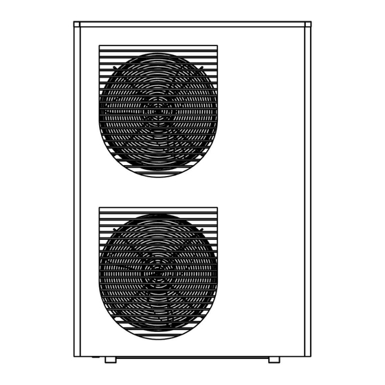
P029. After screeding drying finished, P029 returned to 0. 5.7 Communication with controller Controller is connected with heat pump RS485-1 by 4 wires, (must in order) max 100m. 6 TECHNICAL SPECIFICATION 6.1 Internal View Master 60/90/120 - 40 -... - Page 42 - 41 -...
- Page 43 Master 180/180T/260T - 42 -...
-
Page 44: System Drawing
6.2 System Drawing - 43 -... -
Page 45: Dimensions(Mm)
6.3 Dimensions(mm) Master 60 Master 90/120 - 44 -... -
Page 46: Maintenance
Master 160/180/180T/260TRI 7 MAINTENANCE 7.1 Maintenance and Cleaning for User It is good practice to inspect your heat pump regularly. Maintenance should be carried out at least annually to maintain a good lifespan of your heat pump. - Regularly clean the Y type filters every 6 months to ensure that the system is clean and to avoid blockage to the system. -
Page 47: How To Get The Most Out Of Your Heat Pump
- Check water pump is functioning properly. Make sure the water pipeline and pipe fittings are not leaking. Clear evaporator of any debris. - Check the various components of the unit work properly. Inspect the pipe joints and valves branch have inflated oil, to ensure no leakage of the refrigerant unit. - Page 48 Option 3. You could decide to operate your home with back ground heat. This means you are always (24 hours a day) putting a trickle heat in your home In all cases it is recommended to maintain a minimum temperature in your home (e.g. 14c to16C) during the evening.
-
Page 49: Appendix I: Wifi Operation
Appendix I: WIFI operation 1. APP download Please go to APP store or Google market and search “Smart Life”, download and install the APP, then start it. 2. Register If you are new user, you will need registering: Register→Input your mobile phone number/Email→Check the agreement→Get verification code→Enter the verification code→Set the password→Complete. - Page 50 3. Add device Step 1: Activate the pairing mode on your heat pump controller according to the following: click to enter following page. Click «Smart» to activate WiFi. The symbol will flash quickly. Note: The blinking will stop when the APP is connected to WiFi. Step 2: Now activate the pairing.
- Page 51 Step 3: If the pairing was successful, you can rename your heat pump per below pictures. 4. Controlling Interface as below shown. You can now control your heat pump from your smartphone. - 50 -...
- Page 52 1) Choice of operating modes You can choose between DHW, Heat, Cool, Heat + DHW, Cool + DHW modes. - 51 -...
Need help?
Do you have a question about the Master 60 and is the answer not in the manual?
Questions and answers