
Summary of Contents for Grohe OPTITEMP TFA-100
- Page 1 OPTITEMP TFA-100 Handbook Temperature field indicator © KROHNE 03/2024 - 4010168001 - MA OPTITEMP TFA-100 R01 en...
- Page 2 All rights reserved. It is prohibited to reproduce this documentation, or any part thereof, without the prior written authorisation of KROHNE Messtechnik GmbH. Subject to change without notice. Copyright 2024 by KROHNE Messtechnik GmbH - Ludwig-Krohne-Str. 5 - 47058 Duisburg (Germany) www.krohne.com 03/2024 - 4010168001 - MA OPTITEMP TFA-100 R01 en...
-
Page 3: Table Of Contents
4.1 Safety instructions......................22 4.2 Grounding ........................22 4.3 Ingress protection ......................22 4.4 Power supply ........................22 4.5 Connection diagram ....................... 23 5 Operation 5.1 Start-up........................... 26 5.2 Normal operation ......................26 03/2024 - 4010168001 - MA OPTITEMP TFA-100 R01 en www.krohne.com... - Page 4 6.8 Disassembly and recycling of the field indicator / field housing........30 7 Technical data 7.1 Technical data tables ..................... 34 7.2 Dimensions ........................37 7.2.1 Field housing......................... 37 7.2.2 Accessories ........................... 39 8 Notes www.krohne.com 03/2024 - 4010168001 - MA OPTITEMP TFA-100 R01 en...
-
Page 5: Safety Instructions
The relevant regulations to which temperature transmitters complies are listed in Declaration of conformity which is downloadable from Krohne website. For proper use of the temperature transmitters with temperature field indicator TFA-100 please look into the respective OPTITEMP temperature transmitters handbook. 03/2024 - 4010168001 - MA OPTITEMP TFA-100 R01 en www.krohne.com... -
Page 6: Safety Instructions From The Manufacturer
Improper installation or operation of the devices (systems) will cause the warranty to be void. The respective "Standard Terms and Conditions" which form the basis for the sales contract shall also apply. www.krohne.com 03/2024 - 4010168001 - MA OPTITEMP TFA-100 R01 en... -
Page 7: Information Concerning The Documentation
This document is provided to help you establish operating conditions, which will permit safe and efficient use of this device. Special considerations and precautions are also described in the document, which appear in the form of icons as shown below. 03/2024 - 4010168001 - MA OPTITEMP TFA-100 R01 en www.krohne.com... -
Page 8: Warnings And Symbols Used
In general, devices from the manufacturer may only be installed, commissioned, operated and maintained by properly trained and authorized personnel. This document is provided to help you establish operating conditions, which will permit safe and efficient use of this device. www.krohne.com 03/2024 - 4010168001 - MA OPTITEMP TFA-100 R01 en... -
Page 9: Device Description
Without TT, without display With TT, with display With TT, without display Table 2-1: Scope of delivery Figure 2-1: Package contents 1 TFA-100 2 Pipe Clamp (Optional) 3 Quick Start guide 03/2024 - 4010168001 - MA OPTITEMP TFA-100 R01 en www.krohne.com... -
Page 10: Product Documentation And Software
• Use a mobile device to scan the Data Matrix code (AutoID) on the nameplate of your product. The web browser will then show a page with all the data related to your product. Download the necessary data. www.krohne.com 03/2024 - 4010168001 - MA OPTITEMP TFA-100 R01 en... -
Page 11: Device Description
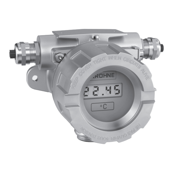
The temperature field indicator OPTITEMP TFA-100 is a heavy-duty instrument for installation directly on pipe or wall. OPTITEMP TFA-100 in general consists of a field housing, window, display module, transmitter and accessories such as cable gland, plug, tag plate and 1.5"...2" pipe clamp. -
Page 12: Types Of Field Housing
• Stainless steel, especially for harsh outdooor environments TFA-100 without window, aluminium TFA-100 with window, aluminium TFA-100 without window, stainless steel TFA-100 with window, stainless steel Table 2-2: Available field housings www.krohne.com 03/2024 - 4010168001 - MA OPTITEMP TFA-100 R01 en... -
Page 13: Cable Gland And Plug
DEVICE DESCRIPTION OPTITEMP TFA-100 2.3.3 Cable gland and plug The cable entries and plugs for OPTITEMP TFA-100 are available in two different types as standard, M20 x 1.5 and 1/2" NPT. Cable entry Plug M20 x 1.5 1/2" NPT Table 2-3: Examples of cable gland and plug 03/2024 - 4010168001 - MA OPTITEMP TFA-100 R01 en www.krohne.com... -
Page 14: Types Of Temperature Transmitters
/ instrument housings with window and in suitable enclosures for field / wall mounting, in an industrial environment. Delivers with a high-contrast, easy-to-read LCD display with white LED-backlight as standard. www.krohne.com 03/2024 - 4010168001 - MA OPTITEMP TFA-100 R01 en... - Page 15 3 Pushbutton with step (increase) function 4 Location of NFC antenna 5 Connection terminals 6 Assembly holes INFORMATION! Consult the relevant display module OPTITEMP LCD-D100 handbook for more detailed information. 03/2024 - 4010168001 - MA OPTITEMP TFA-100 R01 en www.krohne.com...
-
Page 16: Pipe Clamp
DEVICE DESCRIPTION OPTITEMP TFA-100 2.3.6 Pipe Clamp OPTITEMP TFA-100 field housing is designed for wall or 1.5"...2" pipe clamp mounting. There are two size of the pipe clamp depending of field housing size. Figure 2-5: 1.5"...2" pipe clamp www.krohne.com 03/2024 - 4010168001 - MA OPTITEMP TFA-100 R01 en... -
Page 17: Nameplate
10 5 Power supply, enclosure rating (IP), and ambient temperature range (Tamb) 6 Built-in transmitter (if applicable) 7 Input / output data and display scale 03/2024 - 4010168001 - MA OPTITEMP TFA-100 R01 en www.krohne.com... -
Page 18: Installation
Always transport temperature field indicator in their original packaging. Do not expose the devices to moisture or vibration during transport. The information that applies to storage also applies to transport. www.krohne.com 03/2024 - 4010168001 - MA OPTITEMP TFA-100 R01 en... -
Page 19: Proper Installation
2 Secure screw M4 preventing field housing cover to be open 3 Grounding terminal 4 Wall mounted details For wall mounting its recommended to use Ø7 mm bolts together with suitable flat washer and a spring washer. 03/2024 - 4010168001 - MA OPTITEMP TFA-100 R01 en www.krohne.com... - Page 20 WARNING! If rotating the indicator more than 180° it can damage the electrical wiring. Do not use any tools to rotate the display, as this may damage the device. www.krohne.com 03/2024 - 4010168001 - MA OPTITEMP TFA-100 R01 en...
-
Page 21: Opening And Closing Field Indicator
• Screw the housing cover back on by hand and secure its position with the secure screw by using a 4 mm hex spanner. 03/2024 - 4010168001 - MA OPTITEMP TFA-100 R01 en www.krohne.com... -
Page 22: Electrical Connections
The only components of a temperature field indicator that require a power supply are the display module and / or any temperature transmitter used. For more detailed information on supplying these components with power, consult the product-specific manuals. www.krohne.com 03/2024 - 4010168001 - MA OPTITEMP TFA-100 R01 en... -
Page 23: Connection Diagram
OPTITEMP TT 33 C / TT 53 C OPTITEMP TT 51 C 2-wire connection 3-wire connection 4-wire connection Thermocouple Table 4-1: Example for sensor connections 1 Optional low sensor isolation detection lead (SmartSense) 03/2024 - 4010168001 - MA OPTITEMP TFA-100 R01 en www.krohne.com... - Page 24 Figure 4-1: TFA-100 connection diagram with in-head 2-wire transmitter 1 Transmitter 2 Power supply (14.5...30 VDC, 22 mA) Figure 4-2: TFA-100 connection diagram with display module 1 Display module 2 Loop power www.krohne.com 03/2024 - 4010168001 - MA OPTITEMP TFA-100 R01 en...
- Page 25 ELECTRICAL CONNECTIONS OPTITEMP TFA-100 Figure 4-3: TFA-100 connection diagram with in-head 2-wire transmitter and display module LCD-D100 1 Display module LCD-D100 2 Transmitter 3 Power supply (14.5...30 VDC, 22 mA) 03/2024 - 4010168001 - MA OPTITEMP TFA-100 R01 en www.krohne.com...
-
Page 26: Operation
The empty enclosure shall be installed to avoid a risk from propagating brush discharges for application in explosive dust atmosphere. For more operation instructions for temperature transmitter and temperature display module please associate with handbooks separately. www.krohne.com 03/2024 - 4010168001 - MA OPTITEMP TFA-100 R01 en... -
Page 27: Service
3 years after delivery of the last production run for the device. This regulation only applies to spare parts which are subject to wear and tear under normal operating conditions. 03/2024 - 4010168001 - MA OPTITEMP TFA-100 R01 en www.krohne.com... -
Page 28: Availability Of Services
• to check and ensure, if necessary by rinsing or neutralising, that all cavities are free from such dangerous substances, • to enclose a certificate with the device confirming that it is safe to handle and stating the product used. www.krohne.com 03/2024 - 4010168001 - MA OPTITEMP TFA-100 R01 en... -
Page 29: Form (For Copying) To Accompany A Returned Device
We have flushed out and neutralized all cavities in the device. We hereby confirm that there is no risk to persons or the environment caused by any residual media contained in this device when it is returned. Date: Signature: Stamp: 03/2024 - 4010168001 - MA OPTITEMP TFA-100 R01 en www.krohne.com... -
Page 30: Disposal
Total 723...2804 1.594...6.182 Metal parts 721...2558 1.590...5.639 Glass 0...241 0...0.531 Silicone 2...4.5 0.004...0.010 Table 6-1: Total weight of TFA-100 housing refer to the table "Parts and weight for TFA-100" below www.krohne.com 03/2024 - 4010168001 - MA OPTITEMP TFA-100 R01 en... - Page 31 (10) (11) (12) (17) (13) (18) (16) (14) (19) (22) (31) (32) (33) (21) (20) (24) (27) (28) (25) (29) (34) (30) (26) (23) Figure 6-1: Disassembly pars of TFA-100 03/2024 - 4010168001 - MA OPTITEMP TFA-100 R01 en www.krohne.com...
- Page 32 Thermoplastic epoxy resin Display module adaper 2 + steel Nylon Display module mounting screw Nylon Display module mounting gasket Thermoplastic Display module adaper 3 Transmitter Refer to transmitter Transmitter 35.20...50.00 0.078...0.110 manual www.krohne.com 03/2024 - 4010168001 - MA OPTITEMP TFA-100 R01 en...
- Page 33 Stainless steel Screw for tag plate Pipe clamp Stainless steel 213.00...240.00 0.470...0.529 1.5"...2" Pipe clamp type small Stainless steel 1.5"...2" Pipe clamp type large Table 6-2: Parts and weight for TFA-100 03/2024 - 4010168001 - MA OPTITEMP TFA-100 R01 en www.krohne.com...
-
Page 34: Technical Data
Transmitters: 36 V Voltage drop 4.5…14.5V depending on configuration, see handbook for the selected parts Galvanic isolation TT 33 C, TT 53 C and TT 51 C: 1500VAC, 1 minute www.krohne.com 03/2024 - 4010168001 - MA OPTITEMP TFA-100 R01 en... - Page 35 Shock resistance According to IEC60721-4-4 Class 4M4 with method IEC 60068-2-27, 15 g / 6 ms Namur Compliance NE21, NE42, NE53, depending on the configuration, see handbook for the selected parts 03/2024 - 4010168001 - MA OPTITEMP TFA-100 R01 en www.krohne.com...
- Page 36 According to ISO9370 Ozone resistance According to ISO1431-1 (2022-06) and ASTM D 1171-18 (2018) Biological resistance According to IEC 60721-3-4, class 4B2 Table 7-1: Technical data tables for OPTITEMP TFA-100 www.krohne.com 03/2024 - 4010168001 - MA OPTITEMP TFA-100 R01 en...
-
Page 37: Dimensions
Dimensions (Aluminium TFA-100 with window) [mm] [inch] 4.33 4.09 4.25 4.92 105.5 4.15 D1, D2, D3 M20 x 1.5 or 1/2" NPT Table 7-3: Dimensions for aluminium TFA-100 with window 03/2024 - 4010168001 - MA OPTITEMP TFA-100 R01 en www.krohne.com... - Page 38 Dimensions (Stainless steel TFA-100 with window) [mm] [inch] 4.21 4.49 5.00 5.71 4.88 D1, D2, D3 M20 x 1.5 or 1/2" NPT Table 7-5: Dimensions for stainless steel TFA-100 with window www.krohne.com 03/2024 - 4010168001 - MA OPTITEMP TFA-100 R01 en...
-
Page 39: Accessories
4.92 1.89 Table 7-6: Dimensions in mm and inch Dimensions (1.5"...2" pipe clamp for stainless steel field indicator) [mm] [inch] 5.00 5.71 1.89 Table 7-7: Dimensions in mm and inch 03/2024 - 4010168001 - MA OPTITEMP TFA-100 R01 en www.krohne.com... - Page 40 Table 7-8: Dimensions in mm and inch Figure 7-7: Cable gland in 1/2" NPT Dimensions (cable gland in 1/2" NPT) [mm] [inch] 0.95 0.51 1/2" NPT Table 7-9: Dimensions in mm and inch www.krohne.com 03/2024 - 4010168001 - MA OPTITEMP TFA-100 R01 en...
- Page 41 1. Side view of the plug in 1/2" NPT 2. Top view of the plug in 1/2" NPT Dimensions (plug in 1/2" NPT) [mm] [inch] 0.59 1/2" NPT 0.39 Table 7-11: Dimensions in mm and inch 03/2024 - 4010168001 - MA OPTITEMP TFA-100 R01 en www.krohne.com...
-
Page 42: Notes
NOTES OPTITEMP TFA-100 www.krohne.com 03/2024 - 4010168001 - MA OPTITEMP TFA-100 R01 en... - Page 43 NOTES OPTITEMP TFA-100 03/2024 - 4010168001 - MA OPTITEMP TFA-100 R01 en www.krohne.com...
- Page 44 KROHNE – Products, Solutions and Services • Process instrumentation for flow, level, temperature, pressure measurement and process analytics • Flow metering, monitoring, wireless and remote metering solutions • Engineering, commissioning, calibration, maintenance and training services Head Office KROHNE Messtechnik GmbH Ludwig-Krohne-Str.
Need help?
Do you have a question about the OPTITEMP TFA-100 and is the answer not in the manual?
Questions and answers