Table of Contents
Advertisement
Quick Links
SM C J M A X 7 0 0 A TV Serv ice M an ual
Standard Motor Corporation
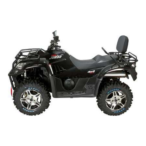
JMAX 700 ATV Service Manual
JMAX702
JMAX701
JMAL701
This service manual contains the technical data of each component inspection and repair for the SMC
JMAX 700 ATV. The manual is shown with illustrations and focused on "Service Procedures",
"Operation Key Points", and "Inspection Adjustment" so that provides technician with service
guidelines.
If the style and construction of the ATV, SMC JMAX 700 ATV, are different from that of the photos,
pictures shown in this manual, the actual vehicle shall prevail. Designs and specifications are subject
to change without notice.
Service Department
Standard Motor Corporation
Advertisement
Table of Contents

Subscribe to Our Youtube Channel
Related Manuals for SMC Networks JMAX 700 Series


Summary of Contents for SMC Networks JMAX 700 Series
- Page 1 SM C J M A X 7 0 0 A TV Serv ice M an ual Standard Motor Corporation JMAX 700 ATV Service Manual JMAX702 JMAX701 JMAL701 This service manual contains the technical data of each component inspection and repair for the SMC JMAX 700 ATV.
- Page 2 SM C J M A X 7 0 0 A TV Serv ice M an ual HOW TO USE THIS MANUAL This service manual describes basic information of different system parts and system inspection & service for SMC JMAX 700 ATV. In addition, please refer to the manual contents in detailed for the model you serviced in inspection and adjustment.
- Page 3 SM C J M A X 7 0 0 A TV Serv ice M an ual SERIAL NUMBER Frame number: Engine number:...
-
Page 4: Table Of Contents
SM C J M A X 7 0 0 A TV Serv ice M an ual CONTENTS Page Content Index 1-1 ~ 1-20 GENERAL INFORMATION 2-1 ~ 2-22 MAINTENANCE INFORMATION 3-1 ~ 3-9 LUBRICANT SYSTEM 4-1 ~ 4-15 FUEL SYSTEM 5-1 ~ 5-10 BODY COVER &... - Page 5 SM C J M A X 7 0 0 A TV Serv ice M an ual 20-1 ~ 20-2 WIRE DIAGRAM...
-
Page 6: General Information
Chapter 1 General Information 1-01. Symbols and Marks 1-02. General Safety 1-03. Service Precautions 1-04. Specifications 1-05. Torque Values 1-06. Troubles Diagnosis 1. General Information This chapter offer you the general information of SMC ATV 700 safety notice, caution and the tools torque setting, please read carefully and make sure you have well acknowledge and skills before start to do any repair/inspection jobs as mentioned at furthering chapters. - Page 7 Chapter 1 General Information 1-02 General information refer to your own safety Below are some of the general information to your own safety during the repair/service time. Carbon monoxide If you must run your engine, ensure the place is well ventilated. Never run your engine in a closed area.
- Page 8 Chapter 1 General Information Battery emits explosive gases; Flame is strictly prohibited. Keeps the place well ventilated when charging the battery. Battery contains sulfuric acid (electrolyte) which can cause serious burns so be careful do not be spray on your eyes or skin. If you get battery acid on your skin, flush it off immediately with water.
- Page 9 Chapter 1 General Information 3. When servicing this ATV, use only metric tools. Metric bolts, nuts, and screws are not interchangeable with the English system, using wrong tools and fasteners may damage this vehicle. 4. Clean the outside of the parts or the cover before removing it from the ATV. Otherwise, dirt and deposit accumulated on the part's surface may fall into the engine, chassis, or brake system to cause damage.
- Page 10 Chapter 1 General Information 10. Note the reassemble position of the important components before disassembling them to ensure they will be reassembled in correct dimensions (depth, distance or position). 11. Components not to be reused should be replaced when disassembled including gaskets, metal seal rings, O-rings, oil seals, snap rings, and split pins.
- Page 11 Chapter 1 General Information 16. The ends of rubber hoses (for fuel, vacuum, or coolant) should be pushed as far as they can go to their connections so that there is enough room below the enlarged ends for tightening the clamps. 17.
- Page 12 Chapter 1 General Information 22. Do not let parts fall down. 23. Battery removal/installation. A. Before battery removal operation, it has to remove the battery negative (-) cable firstly. Tools like open-end wrench do not contact with body to prevent from short-circuit and create spark.
- Page 13 Chapter 1 General Information C. Make sure if the connector pins are bent, extruded or loosen. D. Insert the connector completely. If there are two lockers on two connector sides, make sure the lockers are locked in properly. Check if any wire loose.
- Page 14 Chapter 1 General Information 28. Do not squeeze wires against the weld or its clamp. 29. Do not let the wire harness contact with rotating, moving or vibrating components as routing the harness. 30. Keep wire harnesses far away from the hot parts. 31.
- Page 15 Chapter 1 General Information 35. Never use wires or harnesses which insulation has been broken. Wrap electrical tape around the damaged parts or replace them. 36. Never clamp or squeeze the wire harness as installing other components. 37. Do not let the wire harness been twisted as installation. 38.
- Page 16 Chapter 1 General Information 1-04 Specification a. jMAX 700 series Dimension(LxWxH) : 2125mm/1225mm/1245mm(701/702); 2125mm/1206mm/1150mm(701/702) Seat height : 930mm(off road); 890mm(off road) Wheel base : 1290mm Ground Clearance : 300mm(off road); 215mm(on road) : Un-laden Mass = 320kg; with fuel Mass = 336 kg (701/702) Weight Un-laden Mass = 343kg;...
- Page 17 Chapter 1 General Information R. Brake operation : Front LH side handle brake lever for rear wheeler/parking brake; R side footrest brake pedal for integrate front and rear wheeler at the same time Tire : Tubeless Front/Rear : (F) AT 25x8-12 (for 12” wheel rim), or AT 26x8-14 (for 14” model) (R) AT 25x10-12 (for 12”...
- Page 18 Chapter 1 General Information Differential gear box : SAE 90 API; at change (0,29L) at disassembly (0,33L) RPM limit : Forward limited 7500 +/- 100 and Reverse speed on 15KM/HR. Radiator (liquid coolant): 2080 c.c. coolant (standard concentration 50%) Reserve tank coolant : 300 c.c. +/- 20cc coolant (standard concentration 50%) Fuel : Unleaded gasoline (#95 Octane or above is recommended) Fuel tank...
- Page 19 Chapter 1 General Information Cylinder head stud bolt (inlet pipe) Cylinder head stud bolt (EX. pipe) Tappet adjustment screw nut Spark plug Oil pump screw Water pump impeller Cover cvt bolt Engine oil draining bolt Engine oil strainer Primary sheave ass”y nut Driven sheave ass”y nut Clutch carrier ass”y nut ACG.
- Page 20 Chapter 1 General Information Thread Dia. Item Q’ty Tor Value (N-m) Remarks (mm) Handlebar upper holder bolt Steering shaft nut Steering tie-rod nut Knuckle nut Steering shaft holder bolt Front wheel nut Front axle castle nut Rear axle castle nut Rear wheel nut Engine hanger nut Drive gear bolt...
- Page 21 Chapter 1 General Information Check and adjustment Fault condition Probable causes Loosen carburetor drain bolt to check if there is gasoline inside ● No fuel in fuel tank ● Check if the pipes, fuel tank to carburetor and intake vacuum, are clogged. ●...
- Page 22 Chapter 1 General Information Check and adjustment Fault condition Probable causes Try gradual acceleration and check engine speed ● Air cleaner clogged ● Poor fuel supply ● Lines in fuel tank evaporation system Engine speed can be Engine speed cannot be clogged ●...
- Page 23 Chapter 1 General Information Check and adjustment Fault condition Probable causes Check ignition timing (using Normal Abnormal ● Incorrect ignition timing (malfunction of CDI or AC alternator) Adjust the air screw of ● Rich mixture (loosen the screw) Good Poor ●...
- Page 24 Chapter 1 General Information E. Clutch, driving and driving pulley FAULT CONDITIONS PROBABLE CAUSES ● Drive belt worn out or deformation ● Ramp plate of movable drive face damaged Engine can be started but ATV can not ● Driving pulley spring broken ●...
- Page 25 Chapter 1 General Information G.Loss power Fault condition Probable causes Check and adjustment Raise wheels off ground and ● Brake dragging ● Damaged wheel bearing Spin freely Abnormal ● Wheel bearing needs lubrication Check tire pressure ● Punctured tire Normal Abnormal Accelerate lightly, engine ●...
-
Page 26: Maintenance Information
Chapter 2 Maintenance Information 2-01. Technical Data 2-02. Periodical Maintenance Schedule 2-03. Fuel Hoses 2-04. Throttle Cable 2-05. Air Cleaner 2-06. Spark Plug 2-07. Valve Clearance 2-08. Carburetor Idle Speed Adjustment 2-09. Ignition System 2-10. Cylinder Compression Pressure 2-11. Drive Belt 2-12. - Page 27 Chapter 2 Maintenance Information 2-01 Technical Data of Oil & Pressure Capacity Fuel Tank Capacity 24000 c.c. Capacity 2500 c.c. Change 2200 c.c. Engine Oil Oil and oil filter 2300c.c. change Capacity 330c.c Front differential oil Change 290c.c Capacity 300 c.c. Rear gear box oil Change 290 c.c.
- Page 28 Chapter 2 Maintenance Information 2-02 Periodical Maintenance Schedule Have your ATV checked, adjusted, and recorded maintenance data periodically by your SMC Authorized Dealer to maintain the ATV at the optimum condition. The above maintenance schedule is established by taking the hours or kilometers as a reference whichever comes first. Item Maintenance 300KM...
- Page 29 Chapter 2 Maintenance Information Fr. & Rr. Steering Knuckle pivot Parking Brake/Throttle cable Stabilizer bushes Transmission Differential gear oil Final gear oil Axle boots CVT driving belt/weight rollers CVT driving Clutch Liquid Cooling system Radiator (coolant level, flow, leakage) Coolant reservoir (level, leakage) Coolant Change every 2 years...
- Page 30 Chapter 2 Maintenance Information b. Carbon deposit removal: remove carbon deposits in cylinder head, piston heads, exhaust system when power is obvious lower than ever. - CAUTION: The user must perform the period check & service and keep the service records all the time, or have SMC dealer for a periodic maintenance program.
- Page 31 Chapter 2 Maintenance Information 2-03 Fuel Hoses Remove the fuel tank cover. Loosen screws and bolts, Remove the tank cover, check all lines, and replace it when they are deterioration, damage or leaking Warning Gasoline is a low ignition material, any kind of fire is strictly prohibited as dealing it.
- Page 32 Chapter 2 Maintenance Information the air cleaner element. Clean the element with non-flammable or high-flash point solvent and then squeeze it for dry. Install back the element, ensure yellow side up. Caution Never use gasoline or acid organized solvent to clean the element. Soap the element into cleaning engine oil and then squeeze it out.
- Page 33 Chapter 2 Maintenance Information 2-07. Valve Clearance Caution Checks and adjustment must be performed when the engine temperature is below 35℃. a. Remove necessary covers & spark plug. b. Remove cylinder head cover. c. Remove cylinder head side cover. d. Turn crankshaft in C.W. direction, i)align the Align “|”...
- Page 34 Chapter 2 Maintenance Information 2-08. Carburetor Idle Speed/ Adjustment Caution Inspection & adjustment for idle speed have to be performed after all parts in engine that Idle Adjust screw needed adjustment have been adjusted. Idle speed check and adjustment have to be done after engine is being warm up.
- Page 35 Chapter 2 Maintenance Information 2-09. Ignition System Caution Engine idling speed and throttle cable free play should be adjusted properly before checking. Connect tachometer and ignition light. Start engine. As engine in idle speed: 1600 rpm, aim at the |F mark “F”...
- Page 36 Chapter 2 Maintenance Information 2-11. Drive Belt a. Release all necessary clamps, ducts & parts. b. Remove left crankcase cover bolts. c. Remove the Moveable driving face. d. Install the bolts into the driven sheave ass’y and tighten the bolts, causing the gap to loosen the belt then remove the belt.
- Page 37 Chapter 2 Maintenance Information 2-12. Brake System (Disk Brake) Brake System Hose Make sure the brake hoses contain no corrosion or leaking oil. Brake Fluid Make sure the brake fluid reservoir top is horizontal. Then check brake fluid level in the brake fluid reservoir.
- Page 38 Chapter 2 Maintenance Information brake system hoses. A vacuum machine applied will be very helpful. e. Closed the drain valve Added Brake Fluid Add brake fluid to UPPER limit level. Recommended brake fluid: DOT4 Caution Use only the designed quality brake fluid: other brake fluids may deteriorate the rubber seals, causing leakage and poor brake performance.
- Page 39 Chapter 2 Maintenance Information Brake Pads Replacement (refer Chapter 14) Make sure the brake lining condition. Replace the lining pads if the brake lining wear limitation groove close to the brake disc. Caution Pads Wear indicator ( or groove ) Do not operate the brake lever after the caliper being removed to avoid pushing out piston.
- Page 40 Chapter 2 Maintenance Information 2-14. Headlight Beam Distance Turn on main switch Headlight beam adjustment. Turn the headlight adjusting screw to adjust headlight beam high. Adjusting screw Caution To adjust the headlight beam follows related regulations. Improper headlight beam adjustment will make in coming driver dazzled or insufficient lighting.
- Page 41 Chapter 2 Maintenance Information 2-16. Suspension Adjustment Warning Do not ride the ATV with poor suspension. Looseness, wear or damage suspension will make poor stability and drive-ability. Always adjust both shock absorbers spring preload to the same setting. Uneven adjustment can cause poor handling and loss of stability.
- Page 42 Chapter 2 Maintenance Information 2-17. Steering Handle 1. Place the machine on a level surface. Check steering assembly bushings Move the handlebar up and down, and /or back and forth. Excessive free play Re-screw the Steering bushings bushings or Replace the steering bushings.
- Page 43 Chapter 2 Maintenance Information The vehicle is equipped with low pressure tires. It’s important that they be inflated correctly and maintained at the proper pressures. Tire pressure check should be done before riding. Follow the size and characteristics as recommended when the tires need to be replaced Tire gauage Checking the tires...
- Page 44 Chapter 2 Maintenance Information Engine oil refer to 3-04. Final gear oil Checking 1) Loosen oil check bolt Note: Do not remove the bolt, otherwise the gear oil may come out. Check bolt Filler bolt 2) Check that gear oil seeps out or not.
- Page 45 Chapter 2 Maintenance Information 2) Install back oil filler bolt and fill oil to differential gear case. Periodic oil change: 290cc Oil change after disassembling: 330cc Recommended oil: SAE 90 API “GL-4” Hypoid gear oil. 3) Replace a new gasket and install back the filler bolt.
- Page 46 Chapter 2 Maintenance Information 2-21. C.V. Joint Boot Check Often to check the C.V joint boot ( front and rear), Damage Replace ( refer to Chapter 17) 2-22. Seat Opening & Installing Opening – Stop the engine and turn the key to the left to engage cable and release seat catch.
- Page 47 Chapter 2 Maintenance Information Note: 2-22 SM C J M A X / J M AL 7 0 0 A TV Service M anual...
-
Page 48: Lubricant System
Chapter 3 Lubricant System 3-01. Mechanism Diagram 3-02. Precautions in Operation 3-03. Troubleshooting 3-04. Engine Oil 3-05. Oil Filter Unit 3-06.Engine Oil Pressure Checking 3-07. Oil Pump 3-08. Oil Delivery Pipe 3-01.Mechanism Diagram Oil Route Oil Route SM C JM A X 7 0 0 A TV Serv ice M an ual... - Page 49 Chapter 3 Lubricant System 3-02.Precautions in Operation General Information This chapter contains maintenance operation for the engine oil pump and gear oil replacement. Specifications Disassembly: 2500 c.c. Engine oil capacity Replacement: 2200 c.c. Replacement with oil filter replaced: 2300 c.c. Oil viscosity SAE 10W-40 MA class (Recommended: Synthetic base)
- Page 50 Chapter 3 Lubricant System 3 - 0 4 . E n g i n e O i l Oil Check Turn off engine, and park the ATV in flat surface. Check oil level with oil dipstick. 1. Screw out the dipstick, wipe out the oil on the dipstick 2.
- Page 51 Chapter 3 Lubricant System 3 - 0 5 .O i lF i l t e r U n i t filter unit Remove the oil filter unit with special tool. Special Service Tool: OIL FILTER WRENCH 1) Same steps to drain out the engine oil as filter wrench 3-04.
- Page 52 Chapter 3 Lubricant System bolt. If no engine oil comes out after one minute turn engine off so that it will not seize. Check the engine oil passages, oil filter unit and oil pump for damage or leakage. After solving the findings, start the engine again and check it again.
- Page 53 Chapter 3 Lubricant System B. Oil Pump Disassembly a. Remove the screw on oil pump cover and remove the cover. pump shaft inner rotor outer rotor b. Remove oil pump shaft, inner rotor, outer rotor and cover. pump body C. Oil Pump Inspection Check the clearance between oil pump body and outer rotor.
- Page 54 Chapter 3 Lubricant System E. Oil Pump Installation 1. Install the oil pump gasket always install the new one. 2. Install the oil pump, and then tighten screws. Torque value:1.0kgf-m 3. Make sure that oil pump shaft can be rotated freely.
- Page 55 Chapter 3 Lubricant System B. Inspect pipe 2 1) delivery pipes pipe 2 bent/crash/damage replace contact face roughness replace 2) union bolts/washers damage/block/crash/roughness replace bolt1,2,3 cooper washer always replace the new one. pipe 2 C. Install oil delivery pipe Sequence steps as below: bolt 1 1) Screw union bolt 1 through delivery pipe pipe 2...
- Page 56 Chapter 3 Lubricant System Notes: SM C JM A X 7 0 0 A TV Serv ice M an ual...
- Page 57 Chapter 4 Fuel System 4-01. Mechanism Diagram 4-02. Precautions in Operation 4-03. Trouble Shooting 4-04. Carburetor Remove / Install 4-05. Carburetor 4-06. Fuel Tank / Sender Unit / Fuel cock 4-07. Air Cleaner 4-01. Mechanism Diagram Fuel tank Sender Unit Fuel Cock Carburetor SM C J M A X -J M AL 7 0 0 A TV Service M anual...
- Page 58 Chapter 4 Fuel System 4-02. Precautions in Operation General Information Warning Gasoline is a low ignition point and explosive materials, so always work in a well-ventilated place and strictly prohibit flame when working with gasoline. Cautions Do not bend off throttle cable. Damaged throttle cable will make unstable drivability. When disassembling fuel system parts, pay attention to O-ring position, replace with new one after re-assembly There is a drain screw in the float chamber for draining residual gasoline.
-
Page 59: Fuel System
Chapter 4 Fuel System 4-03. Trouble Shooting Mixture too lean Poor engine start Clogged fuel injector No fuel in fuel tank Vacuum piston stick and closed Clogged fuel tube Malfunction of float valve Too much fuel in cylinder Fuel level too low in float chamber No spark from spark plug(malfunction of Clogged fuel tank cap vent ignition system ) - Page 60 Chapter 4 Fuel System 4-04. Carburetor Remove / Install A. Removal. a. Remove the R/L side cover. b. Disconnect the throttle cable from Carburetor: 1. Remove 3 screws from throttle cap on carburetor, 2. Remove the throttle seat (PIN) and cable. 3.
- Page 61 Chapter 4 Fuel System 4-05. Carburetor Disassembly. 4-05-01. Air Cut-Off Valve A. Disassembly 1. Remove 2 screws. 2 screws Remove air cut-off valve cover, spring and valve. B. Inspection air cut-off valve Check the valve/spring are in normal. If normal, it will restrict air-flow.
- Page 62 Chapter 4 Fuel System 2. Remove screws (2 screws) of vacuum chamber cover and the cover. 2 bolts Vacuum chamber 3. Remove compress spring and vacuum piston. 4. Remove fuel needle seat, spring, and injector needle. B. Inspection seat 1. Check if the vacuum piston for wear out, crack or other damage.
- Page 63 Chapter 4 Fuel System 4-05-03 Float chamber A. Disassembly 1. Remove 4 mounting screws and remove float chamber cover. 4 screws 2. Remove the pan head screw and them take out the float pin, float body and float valve. Float valve Float B.
- Page 64 Chapter 4 Fuel System b. Main jet, Main Jet extender, Needle jet, pilot jet slow jet. Needle jet 1. Remove Main jet, Main Jet extender, Needle jet, pilot jet slow jet for maintenance (clean and inspection for clog) Extender, Main Jet Caution Take care not to damage jets and adjust screw.
- Page 65 Chapter 4 Fuel System Carburetor adjustments: Following adjustments must be made after installation of carburetor. Throttle valve Throttle cable adjustment. stopper Check free movement on throttle Idle Speed adjust screw valve, if stick, replace it. turn the stopper to be just touching the throttle valve when the cable release.
- Page 66 Chapter 4 Fuel System 4-06. Fuel Cock / Fuel Tank / Fuel Unit Before the fuel tank remove, please remove the side cover, top cover (as mentioned at chapter 4-06-01. Fuel cock a. Fuel drain out and hose disconnect FUEL HOSE CLAMP (CLIP) 1.
- Page 67 Chapter 4 Fuel System counter-clockwise direction to remove the fuel cock. d. Inspection. 1. Check the fuel cock if any fuel leaking or clogged 2. Check the fuel filter screen if broken. 3. Check the O-ring if damage. 4. Check the fuel hose if cracks or damage. Replace with new if problem found.
- Page 68 Chapter 4 Fuel System 4-06-03. Fuel tank Before removal the fuel tank, please process the fuel drain out and fuel hose disconnect / fuel cock removal as previous 4-06-01 mentioned. a. Removal 1. Disconnect the sender unit wire coupler from tank. 2.
- Page 69 Chapter 4 Fuel System 4-07. Air Cleaner a. Removal 1. Loosen the clamp on air cleaner air duct in connecting with carburetor 2. Release the hose clamp (Clip) on the breathe hose in connecting between cylinder head and air cleaner, then disconnect the breathe hose from air cleaner.
- Page 70 Chapter 4 Fuel System element should be wet but not dropping. 7. Reinstall the element to the element guide. 8. Reinstall the element assembly and parts removed for access. Caution Never use gasoline or acid organized solvent to clean the element. Element should be yellow part side up.
- Page 71 Chapter 4 Fuel System Notes: 4-15 SM C J M A X -J M AL 7 0 0 A TV Service M anual...
- Page 72 Chapter 5 Body cover & Engine removal 5-01. Precautions in Operation 5-02. Removal of Engine 5-03. Engine Installation 5-01. Precautions in Operation General Information The engine has to be supported with special service tools that can be lifted or adjustable. The following parts can be serviced as engine being mounted on frame: Carburetor Start motor.
-
Page 73: Body Cover & Engine Removal
Chapter 5 Body cover & Engine removal 5-02. Engine Removal a. Remove the seat. Switch the ignition switch from “off” to “seat open” to release the seat. Remove out the seat. ative(-) b. Remove the battery Remove the battery cord. Firstly remove negative terminal (-) and then remove the battery positive (+) Positive(+) - Page 74 Chapter 5 Body cover & Engine removal e. Remove the front carrier Remove out 4 flange bolts from front carrier. Remove out the front carrier f. Remove out the front top cover. Screw out 4 tapping screws as photo show. Remove out the front too cover.
- Page 75 Chapter 5 Body cover & Engine removal i. Remove the fuel tank. Switch off the fuel cock to OFF Disconnect the fuel unit wire connector Disconnect the fuel hose between fuel cock and carburetor. Remove the fuel tank. (for detail message, please refer to 4-06) j.
- Page 76 Chapter 5 Body cover & Engine removal light, winkers. Remove the rear fender. m. Remove the muffler Loose the clamp at connecting side between exhaust pipe and muffler. Remove the two flange bolts on the muffler side. Disconnect the muffler from front exhaust pipe.
- Page 77 Chapter 5 Body cover & Engine removal remove 3 screws and remove the throttle cable on the throttle controller box on carburetor remove the choke cable from carburetor remove the 2 clamps on the air cleaner breather tube and intake pipe. Remove the carburetor.
- Page 78 Chapter 5 Body cover & Engine removal r. remove the gear shifter and gear shifting limiter, brake switch bracket from engine. Screw out the flange bolt from shift lever, and remove out gear shifting rod. Screw out 2 bolts to remove out shift lever limiter.
- Page 79 Chapter 5 Body cover & Engine removal t. remove the front and rear drive shaft connector. Remove 4 socket bolts on the front universal joint at front gear box side, and remove the front drive shaft. Remove 4 socket bolts on the universal joint in connecting with engine output shaft side and then remove the rear propeller shaft.
- Page 80 Chapter 5 Body cover & Engine removal Caution Be careful when removing and installing the engine. Do not crash the body covers when removal and installing. Follow the recommended torque values for all installing engine and covers. Follow the recommended loctitie glue applying when installing.
- Page 81 Chapter 5 Body cover & Engine removal NOTE: 5-10 SM C J M A X 7 0 0 A TV Serv ice M an ual...
-
Page 82: Cylinder Head/Valves
Chapter 6 Cylinder Head/Valves 6-01. Mechanism Diagram 6-02. Precautions in Operation 6-03. Troubleshooting 6-04. Cylinder Head Removal 6-05. Cylinder Head Inspection 6-06. Valve Seat Inspection and Service 6-07. Cylinder Head Reassembly 6-01. Mechanism Diagram SM C J M A X 7 0 0 A TV Serv ice M an ual... - Page 83 Chapter 6 Cylinder Head/Valves 6 - 0 2 . P r e c a u t i o n s i n O p e r a t i o n General Information This chapter is contained maintenance and service for cylinder head, valve, and camshaft as well ●...
- Page 84 Chapter 6 Cylinder Head/Valves 6 - 0 3 .T r o u b l e s h o o t i n g Engine performance will be affected by troubles on engine top parts. The trouble usually can be determined or by performing cylinder compression test and judging the abnormal noise generated.
- Page 85 Chapter 6 Cylinder Head/Valves 6-04. Cylinder Head Removal a. Remove the engine from the frame. (Refer to chapter 5) Thermostat b. Remove the thermostat Remove 2 thermostat bolts and open the Thermostat bolts thermostat cover. Remove the thermostat. c. Remove the cam chain tensioner Remove the 2 flange bolts Remove the cam chain tensioner.
- Page 86 Chapter 6 Cylinder Head/Valves f. Remove the Cylinder head side cover. Remove the 3 side cover mounting blots of cylinder head, Then remove the side cover of cylinder head. g. Piston TDC position align Remove tappet adjusting cap on right crankcase cover, and turn the crank shaft.
- Page 87 Chapter 6 Cylinder Head/Valves j. Remove cylinder head gasket and 2 dowel pins. k. Remove cam chain guide. l. Clean up residues from the matching surfaces of cylinder and cylinder head. Caution Do not damage the matching surfaces of cylinder and cylinder head. Avoid residues of gasket or foreign materials falling into crankcase as cleaning.
- Page 88 Chapter 6 Cylinder Head/Valves Use a valve cotter remove & assembly tool to press the valve spring, and then remove valves. Caution In order to avoid loose of spring elasticity, do not press the spring too much. Thus, press lengths is based on the valve cotter in which can be removed.
- Page 89 Chapter 6 Cylinder Head/Valves 6-05. Parts inspection rounded a. Cylinder Head Inspection Check if spark plug and valve holes are cracked. Eliminate carbon deposits by a rounded scraper then clean it in solvent. avoid damaging valve seats/guide plug threads and matching surface Eliminate mineral deposits/rust on wate jacket.
- Page 90 Chapter 6 Cylinder Head/Valves d. Rocker Arm Shaft Measure the active O.D. of the cam rocker arm shaft and cam rocker arm. Service Limit: Replace when it is less than 12.973 mm. Calculate the clearance between the rocker arm shaft and the rocker arm. Service Limit: Replace when it is less than 0.06mm.
- Page 91 Chapter 6 Cylinder Head/Valves g. Valve guide 5.0mm valve guide reamer Caution Before measuring the valve guide, clean carbon deposits with reamer. Tool: 5.0 mm valve guide reamer Measure and record each valve guide inner diameters. Service limit: 5.05 mm The difference that the inner diameter of valve guide deducts the outer diameter of valve stem is the clearance between the...
- Page 92 Chapter 6 Cylinder Head/Valves Clean up the emery after corrected, and apply with engine oil onto contact faces of valve and valve seat. Remove the valve and check its contact face. Caution Replace the valve with a new one if valve is roughness, wear out, or incomplete contacted with valve seat.
- Page 93 Chapter 6 Cylinder Head/Valves Use 45° cutter to grind the valve seat to specified width ( 1.0mm). Caution 45 ゚ Make sure that all roughness and uneven faces had been grounded. Grind valve seat again if necessary. Coat the valve seat surface with red paint.
- Page 94 Chapter 6 Cylinder Head/Valves valve springs retainer 6-07. Cylinder Head Reassembly Valve cotter Valve stem seal a. install the valve Inlet valve Lubricate valve stem with engine oil, spring seat and then Insert the valve into valve guide. valve spring Install new valve stem oil seal.
- Page 95 Chapter 6 Cylinder Head/Valves b. I nstall the camshaft and rocker arm Apply engine oil to the bearing of camshaft. Insert the camshaft to the cylinder head. Be careful to push slightly to avoid the damage. Insert the Rocker arm shaft, the rocker arm and plate washer between rocker arm, .adjust the ditch of rocker arm shaft to the vertical...
- Page 96 Chapter 6 Cylinder Head/Valves Caution 1. Do not damage the matching surfaces of cylinder and cylinder head. 2. Avoid residues of gasket or foreign materials falling into crankcase as cleaning. Install 4 washers and bolts to cylinder head. Tighten the bolts to the specified torque in three steps ( 4=>5=>6kgf-m) in the proper tightening sequence as shown.
- Page 97 Chapter 6 Cylinder Head/Valves f. install the cam chain tensioner Loosen auto tensioner adjustment bolt and remove bolt and spring. convex checking : push the convex and test teeth bar smoothly. check the spring Install tensioner with gasket and install spring and adjustment bolt with oil adjusting bolt ring.
- Page 98 Chapter 6 Cylinder Head/Valves j. Install and tighten spark plug (NGK CR7E) Torque value: 1.1~1.3kgf-m Caution This model is equipped with more precision 4-valve mechanism so its tighten torque cannot be exceeded standard value in order to avoid causing cylinder head deformation, engine noise and leaking so that vehicle performance be affected.
- Page 99 Chapter 6 Cylinder Head/Valves NOTE: 6-18 SM C J M A X 7 0 0 A TV Serv ice M an ual...
-
Page 100: Cylinder/Piston /Ring
Chapter 7 Cylinder/Piston/Ring 7-01. Mechanism Diagram 7-02. Precautions in Operation 7-03. Trouble Shooting 7-04. Cylinder and Piston Removal 7-05. Inspection on Cylinder /Piston/Piston Ring 7-06. Piston Ring Installation 7-07. Piston Installation 7-08. Cylinder Installation 7-01. Mechanism Diagram 1.0 kg-m /10 Nm 1.8.~2.2kg-m SM C J M A X 7 0 0 A TV Serv ice M an ual... - Page 101 Chapter 7 Cylinder/Piston/Ring 7-02. Precautions in Operation General Information Both cylinder and piston service cannot be carried out when engine mounted on frame. Specification Unit:mm Item Limit 100.1 Cylinder Bend 0.05 Clearance between Top ring 0.13 piston rings ring 0.13 Top ring 0.70 Piston /...
- Page 102 Chapter 7 Cylinder/Piston/Ring 7-04. Cylinder and Piston Removal a. Remove the cylinder head (refer to chapter b. release the hose clamps and then remove the Water pump EX hose from cylinder. c. Screw out the 3 flange bolts (M6*25) on cylinder outer side.
- Page 103 Chapter 7 Cylinder/Piston/Ring In the 3 positions, top, center and bottom, of cylinder, measure the X and Y values respective in the cylinder. Service limit: 100.1 mm Center Bottom b. Check cylinder if warp. Service limit: 0.05 mm c. Measure clearance between piston rings and grooves.
- Page 104 Chapter 7 Cylinder/Piston/Ring angle on the cylinder bore) then measure ring end gap by feeler gauge. Top ring with chrome coating is different from 2 ring. Service Limit: Top ring: 0.70 mm 2nd ring: 0.80 mm Note: You can’t measure the end gap on the expander spacer of the oil ring.
- Page 105 Chapter 7 Cylinder/Piston/Ring i. Measure cylinder bore diameter Measure the average value “R” at 50mm from the top of cylinder by cylinder bore gauge. R = (X+Y)/2 Standard cylinder bore dimater: 100.005 ~ 100.055mm Service limit : 100.1mm Out of specification rebore or replace j.
- Page 106 Chapter 7 Cylinder/Piston/Ring 7-06. Piston Ring Installation Clean up piston top, ring groove, and piston surface. Install the piston ring onto piston carefully. Place the openings of piston ring as diagram shown. Caution Do not damage piston and piston rings in installation. All marks (RN )on the piston rings must be forwarded to up side.
- Page 107 Chapter 7 Cylinder/Piston/Ring 7-07. Piston set Installation Before installation of Piston set onto connecting rod, clean up all residues and foreign materials on the contact surface of crankcase. Pay attention not to let these residues and foreign materials fall into crankcase.
- Page 108 Chapter 7 Cylinder/Piston/Ring Apply some engine oil to inside of cylinder, piston and piston rings. Use piston clamper to hold the piston ring and install the cylinder parallel and gentle to avoid damage the cylinder inner wall. When the piston rings are all installed inside cylinder, remove the clamp and push gently to install cylinder to crankcase.
- Page 109 Chapter 7 Cylinder/Piston/Ring NOTE: 7-10 SM C J M A X 7 0 0 A TV Serv ice M an ual...
-
Page 110: Cvt Driving System
Chapter 8 CVT driving System 8-01. Mechanism 8-02. Maintenance Description 8-03. Trouble Diagnosis 8-04. Left Crankcase Cover 8-05. Primary Sheave , Driven Sheave & Drive Belt 8-06. Clutch Housing, One Way Clutch and Clutch Carrier 8-01. Mechanism Diagram... - Page 111 Chapter 8 CVT driving System 8-02. Maintenance Description Precautions in Operation General Information Drive face, clutch outer, and driven pulley can be serviced on the vehicle. Drive belt and drive pulley must be free of any grease. 8-03. Trouble Diagnosis Engine can be started but ATV can not be moved 1.
- Page 112 Chapter 8 CVT driving System 8-04. Left Crankcase Cover a. Left crankcase cover removal 1. Release the rear air duct clamps and disconnect the CVT rear air duct from left crankcase. (if engine is not removed). 2. Remove left crankcase cover flange bolts M6*55 (15olts).
- Page 113 Chapter 8 CVT driving System 5. Tighten the flange bolt by steps of cross direction Torque: Flange bolt M6*55. 1.0kg-m /10Nm. 8-05. Primary Sheave , Driven Sheave & Drive Belt, CVT cooling fan plate. holder 8-05-01 Removal 1. Hold the primary sheave ass’y by holder (special tool), and loosen &...
- Page 114 Chapter 8 CVT driving System 1. Check the drive belt for crack or wear. Replace it if necessary. 2. Measure the width of drive belt as diagram shown. 3. Refer to 2-11. Service Limit: 28.3 mm Replace the belt if exceeds the service limit. Caution Using the genuine parts for replacement.
- Page 115 Chapter 8 CVT driving System c. Driven Sheave Assy, Slide Collar, O-ring cam groove and Oil seal. 1. Driven Sheave Assy Check following items: guide pin Operation smooth on cam groove and guide pin. If both sheave surfaces are scratch or damage.
- Page 116 Chapter 8 CVT driving System Torque: flange bolt M6x12mm: 1.0kg-m /10Nm 3. Insert the O-ring to the primary drive gear. 4. Put on the primary fix sheave, driven sheave ass’y and driving belt. Expand the driven sheave gap for driving belt to hold at inner sheave surface ( refer to 2-11 ).
- Page 117 Chapter 8 CVT driving System 2. Pull the clutch housing shaft to remove the clutch cover, clutch housing and one way clutch ( it might be inside clutch housing ). 3. Take out the clutch cover gasket, 2 dowel pin 4.
- Page 118 Chapter 8 CVT driving System and hold the clutch carrier ass’y. Note: The one-way clutch bearing should be installed with the flange side “ → “ facing toward the clutch carrier. b) When turning the clutch housing clockwise X, the clutch housing should turn freely.
- Page 119 Chapter 8 CVT driving System Installation 1. Install the two rings onto the clutch carrier collar, and then put onto the crankshaft. 2. Use tool to install the clutch carrier collar with rings. Ensure the right direction to the crankshaft. 3.
- Page 120 Chapter 8 CVT driving System NOTE: 8-11...
-
Page 121: Generator/Starting Clutch/Water Pump
Chapter 9 A.C. Generator / Starting Clutch/Water Pump 9-01. Mechanism Diagram 9-02. Precautions in Operation 9-03. Right Crankcase Cover & A.C.Generator 9-04. A.C.G Fly Wheel & One-Way Clutch 9-05. Starter Clutch Gear & Starter Reduction Gear 9-01. Mechanism Diagram A.C.G. Cap GASKET, R CRANKCASE CAP, TAPPET Flywheel Comp... - Page 122 Chapter 9 A.C. Generator / Starting Clutch/Water Pump 9-02. Precautions in Operation General information Refer to chapter 18: The troubleshooting and inspection of alternator Refer to chapter 18: The service procedures and precaution items of starter motor Tools Special tools A.C.G.
- Page 123 Chapter 9 A.C. Generator / Starting Clutch/Water Pump 9-03. Right Crankcase Cover & A.C. Generator a. Removal 1. Drain the engine oil 2. Unscrew 12 mounted flange bolts from the right crankcase cover and then remove the right crankcase cover with A.C. Generator. Note: Always working in a crisscross pattern, loosen each bolt 1/4 of a turn.
- Page 124 Chapter 9 A.C. Generator / Starting Clutch/Water Pump 2. Use flywheel puller to remove flywheel. Screw in the flywheel flange bolt some threads by hand, Screw in flywheel puller clockwise to the crankshaft. Use wench to hold the A.C.G. flywheel puller and clockwise screw in the push shaft of A.C.G.
- Page 125 Chapter 9 A.C. Generator / Starting Clutch/Water Pump d. Installation 1. Put the one way clutch into clutch outer race and then install to A.C.G. Flywheel. Tighten the 3 socket bolts with glue. Torque value: Socket boot M8*23: 3.3kgf-m 2. Align the flywheel groove with woodruff key, and then install the flywheel Ass’y (including one-way clutch) onto the R.
- Page 126 Chapter 9 A.C. Generator / Starting Clutch/Water Pump b. Inspection 1. Starting clutch driven gear tooth gear tooth - wear/damage replace inside contact hole - wear/damage replace outside contact surface - wear/pitting/damage replace 2. Clutch reduction gear set tooth and shaft for wear or damage.
- Page 127 Chapter 9 A.C. Generator / Starting Clutch/Water Pump NOTE: SM C J M A X 7 0 0 A TV Serv ice M an ual...
- Page 128 Chapter 10 Gear Shifting Box 10-01. Mechanism 10-02. Trouble Diagnosis 10-03. Gear box disassembly 10-04. Gear box Inspection 10-05. Gear box Reassembly 10-01. Mechanism Diagram SHIFT LEVER COVER, GEARBOX Dowel Pin MANUAL SHIFT SPINDLE COMP Folder (Clip) DRIVEN GEAR, DRUM Oil Seal Gasket, gear box SHIFT FORK COMP...
- Page 129 Chapter 10 Gear Shifting Box 10-02. Trouble Di ag n o s i s Engine can be started but vehicle cannot move. Damaged gear shift system Damaged drive gear Burnt out drive gear Wrong installation Noise Worn or burnt gear Worn gear Gear oil leaks Excessive gear oil.
- Page 130 Chapter 10 Gear Shifting Box 10-03. Gear Shifting Box Disassembly a. Loose and remove the flange bolt M6*16 to disconnect the gear shift plate and gear shift lever from engine b. Screw out 5 flange bolts (M6*30) on the gear box cover, and open the gear box cover.
- Page 131 Chapter 10 Gear Shifting Box 10-05. Gear box re-assembly 1. Put shift drum driven gear on the gear shifting drum 2. Put the shift drive spring, plate washer onto shift driven gear and lock by cir-clip. the two ends of spring should be pushed into the groove of gear shifting drum.
- Page 132 Chapter 10 Gear Shifting Box NOTE: 10-5 SM C J M A X 7 0 0 A TV Serv ice M an ual...
- Page 133 Chapter 11 Transmission 11-01. Mechanism 11-02. Precautions in operation 11-03. Trouble Diagnosis 11-04. Transmission Disassembly 11-05. Transmission Inspection 11-06. Transmission Reassembly 11-01. Mechanism Diagram 11-1 SM C J M A X 7 0 0 A TV Serv ice M an ual...
-
Page 134: Gear Shifting Box
Chapter 11 Transmission 11-02. Pr ec au t i o n s i n Op er at i o n This Section concerns disassembly of the crankcase for repair purpose. Remove following components before disassembling crankcase. -Engine remove Chapter 5 -Cylinder head Chapter 6 -Cylinder and piston... -
Page 135: Transmission
Chapter 11 Transmission 11-04.Transmission Disassembly Note: Before disassembly of the transmission, please refer below chapter to remove necessary parts. Chapter 3 Lubrication System Chapter 8 CVT driving system Chapter 9 A.C.Generator Chapter 10 Shifting Gear box Lie down the disassembled engine right side up as picture. - Page 136 Chapter 11 Transmission To fix the flat plate to the crankcase R by four bolts and insert the tool to crankshaft. Fix the shaft and screw in the nut step by step ( 3~5 times )to detach the crankcase R evenly. Remove the dowel pins and crankcase L separate crankcase L /R.
- Page 137 Chapter 11 Transmission f. Pull and remove the reverse idle gear axle ass’y and Primary drive gear Ass’y. g. Push the gear and clip out the circlip to remove the gear park/spring. h. Remove out the bolt/cooper washer/spring/ball by wrench. i.
- Page 138 Chapter 11 Transmission l. Knock back the nut and remove the nut on drive bevel gear on the right crankcase, then remove the gear and the shim. Take a note on the grade of shim and put the same grade of shim when reassembling. shim grade m.
- Page 139 Chapter 11 Transmission 11-05.Transmission Inspection a. Shift drum -- groove scratches/wear/damage replace b. Shift fork/ guide bar/spring Shift fork groove follower wear/damage replace guide bar fork pawl scoring/bend/wear/damage follower replace pawl Guide bar – bends replace check the movement with fork forward and backward Spring –...
- Page 140 Chapter 11 Transmission d. Check if the reverse shaft, oil passage and gear teeth – bend, clogged, wear or damage blow or replace e. Check if the drive shaft and gear -- burn, wear or damage replace f. Gear park checking – mated dogs rounded -- edge/cracks/missing portion replace...
- Page 141 Chapter 11 Transmission check retainer – bent replace check o-ring/oil seal conditions remark the grade on the shims always replace a new nut j. Check oil filter and relief valve Oil filter contaminants clean with oil clogged blow by compression air damage replace always replace a new o-ring...
- Page 142 Chapter 11 Transmission install pinion gear & washer apply the loctitie glue on threads( or nut ) & tightened the nut. Secure the nut after tightened. Note: always replace a new nut. install the housing set to the crankcase apply the loctitie glue on bolts and tightened.
- Page 143 Chapter 11 Transmission pinion gear install pinion gear & housing ( assembled with bearings/ collar/ oil seal) install coupling and o-ring and washer apply loctite glue to the nut and lock the nut. install middle driven shaft ass’y to crankcase L put the o-ring t the ass’y &...
- Page 144 Chapter 11 Transmission install the primary gear & reverse idle gear apply enough oil to all installations before combining crankcase L & R. Combine crankcase L & R ass’y Before installing and torquing the crankcase holding bolts, be sure to check whether the transmission is functioning properly by manually rotating the shift cam in both direction.
- Page 145 Chapter 11 Transmission apply oil to o-rings and insert the switches to the should-be positions. long pin side of selector switch is neutral gear. follow the specified torque M8*65 2.3kgf-m M6*65 1kgf-m M6*16 1kgf-m M6*12 1kgf-m check the crankshaft and transmission operation by manual Unsmooth operation repair...
- Page 146 Chapter 11 Transmission Manufacture remark “ shim grade “ posed on the crankcase. Just for a reference. to help a parts ordering. 11-14 SM C J M A X 7 0 0 A TV Serv ice M an ual...
- Page 147 Chapter 11 Transmission NOTE: 11-15 SM C J M A X 7 0 0 A TV Serv ice M an ual...
- Page 148 Chapter 12 Crankshaft & Balancer 12-01. Mechanism Diagram 12-02. General Information 12-03. Trouble Diagnosis 12-04. Removal of Crankshaft & Balancer 12-05. Inspection 12-06. Re-assembly 12-01. Mechanism Diagram 12-1 SM C J M A X 7 0 0 A TV Serv ice M an ual...
- Page 149 Chapter 12 Crankshaft & Balancer 12-02. General Information Operational precautions This Section concerns disassembly of the crankcase for repair purpose. Remove following components before disassembling crankcase. -Engine remove Section 5 -Cylinder head Section 6 -Cylinder and piston Section 7 -Drive face and driven pulley Section 8 -AC generator/Start one way clutch Section 9...
- Page 150 Chapter 12 Crankshaft & Balancer 12-04. Removal of Crankshaft & Balancer a. Separating crankcase 1. Place left crankcase downward and right crankcase up. 2. Loosen 17 bolts on the right crankcase. 3. Tap the right crankcase with a plastic hammer to remove it.
- Page 151 Chapter 12 Crankshaft & Balancer 12-05. Inspection a. Balancer check the balancer shaft – damage/ cracks/ bent replace whole set check the drive gear – damage/wear replace whole set excessive noise during operation replace whole set check the pin and spring – wear/damage replace Note: align the point to buffer boss and drive gear when installing back.
- Page 152 Chapter 12 Crankshaft & Balancer replace oil passage – clogged blow by compressed air heat burn replace 12-06. Re-assembly Install crankshaft to crankcase L Use special tool to pull the crankshaft from right side to the bearings race. Note: ensure the connecting rod not to bump crankcase.
- Page 153 Chapter 12 Crankshaft & Balancer NOTE: 12-6 SM C J M A X 7 0 0 A TV Serv ice M an ual...
-
Page 154: Liquid Cooling Syste
Chapter 13 Liquid Cooling System 13-01 General Information 13-02 Technical Specification 13-03 Trouble Diagnosis 13-04 Coolant Check/Replacement 13-05. Radiator Cap/ Reservoir Tank 13-06. Radiator / Cooling Fan 13-07. Water Pump 13-08. Thermostat/Thermostat Sensor 13-01. General Information WARING: Removing the radiator cap while the engine is hot can allow the coolant to spray out, seriously scalding you. - Page 155 Chapter 13 Liquid Cooling System 13-02. Technical Specification Item Specification Pressure to open filler cap 1.1±0.15 kgf/cm Capacity of coolant: Engine + radiator 2,080 +/- 20 c.c. Reservoir Tank 300cc +/- 20 c.c. Begins to activate at 71±1.5℃ Thermostat Thermos switch (Fan Switch) Begins to activate at 85±3℃...
- Page 156 Chapter 13 Liquid Cooling System 13-03. Trouble Diagnosis a. The engine temperature is too high The water thermometer, Thermo Switch (Fan Switch) sensor do not work properly. The thermostat is stuck to close. Insufficient coolant. The water hose and jacket are clogged. Fan motor malfunction.
- Page 157 Chapter 13 Liquid Cooling System d. Trouble Diagnosis for Cooling System The temperature indicated is too high A. Stop and waiting for the A1.Refill the radiator with engine is completely coolant then check for Water leaking problem cooled down, open cap to check the capacity of B.
- Page 158 Chapter 13 Liquid Cooling System Preceding page E. Keep eng. 3000~4000 E-1.Measure thermal switch Replace thermal switch rpm and inspect cooling to confirm voltage be changed (12→0V)? fan was operating after the temperature gauge E-2.Connect cooling fan Replace cooling fan F.
- Page 159 Chapter 13 Liquid Cooling System 13-04. Coolant Check / Replacement Warning Never attempt to work on the cooling system unless the engine is completely cooled down. a. Coolant check Check the coolant liquid level inside the reservoir tank. Add coolant to the proper level between Min.
- Page 160 Chapter 13 Liquid Cooling System Torque: 1 kgf-m 3. Refilling system with recommended coolant through the filler opening up to the filler neck. Bleed the air from the system as follow: a. Start the engine and let it idle for 2~3 minutes.
- Page 161 Chapter 13 Liquid Cooling System Relief pressure for the filler cap: 1.1 kgf/cm Apply pressure to the radiator, engine and water hose to check for any leakage Caution High pressure may damage the radiator. Never use pressure which exceeds 1.1 kg/cm If the system fails to maintain the specified pressure for at least 6 seconds, repair or replace parts.
- Page 162 Chapter 13 Liquid Cooling System b. Inspection 1. Check the reservoir tank if any cracks, deteriorates or broken, replace with new if necessary. 2. Check the reservoir tank water hose (to radiator filler tube) if any cracks, leaking. Replace with new if necessary. 3.
- Page 163 Chapter 13 Liquid Cooling System 2. Disconnect the water hose of reservoir Radiator Cap Set tank water from radiator filler tube. 3. Remove the Hex. bolt with washer (M6*16) on the radiator cap set and Water Pump disconnect the radiator cap set from EX Hose chassis.
- Page 164 Chapter 13 Liquid Cooling System 13-06-02 Inspection a. Radiator 1. Use air gun to blow the dust-mud on the radiator and gently clean it by water. 2. Check the radiator if leaking, clogged or damage. Straighten any flattened fins with a thin flat-head screwdriver.
- Page 165 Chapter 13 Liquid Cooling System 13-06-03 Installation of Radiator Assy. Install the removed parts in the reverse order of removal. Install radiator in the reverse order of removal. Upon completion, re-fill the coolant as mentioned at 13-04. Installation Torque: a. Hex. Bolt with Washer (M6*22) for Radiator:0.7 kgf-m b..
- Page 166 Chapter 13 Liquid Cooling System pump seal. 2. If after check the seal is confirm ok, then Cylinder Head Gasket keep to have advance service check on the cylinder head gaskets of sealing between the cylinder / cylinder head side. a.
- Page 167 Chapter 13 Liquid Cooling System Remove the thermostat cover (2 bolts) on the cylinder head. Remove the thermostat. b. Removal of thermo sensor. 1. Use wrench to remove the thermo sensor from cylinder head side. When removing, take care of the ground terminal and wave washer.
- Page 168 Chapter 13 Liquid Cooling System 3. Installation Install the thermostat. install the thermostat ① with its breather hole (a) facing up to the inley (b) of cylinder head. Install the thermostat cover. (2 bolts) Torque: Flange Bolt (M6*25): 1.0 kg-m/10Nm Install the wave washer, ground terminal and then the thermo sensor with specific torque:...
- Page 169 Chapter 13 Liquid Cooling System NOTE: 13-16 SM C J M A X -J M AL 7 0 0 A TV Service M anual...
-
Page 170: Front Wheel/Brake
Chapter 14 Front Wheel/Brake 14-01. Mechanism Diagram 14-02. Maintenance Description 14-03. Trouble Diagnosis 14-04. Front Wheel/ Tire 14-05. Front Wheel Hub 14-06. Disk Brake System Inspection 14-07. Adding Brake Fluid 14-08. Front Brake fluid replacement / Air-bleed 14-09. Front Brake Caliper 14-10. - Page 171 Chapter 14 Front Wheel/Brake 14-02. Maintenance Description a. Operational precautions Caution During servicing, keep oil or grease off the brake pads and disk. Drain the brake fluid from the hydraulic brake system before disassembly. Clean the contaminated brake disk with high-performance brake degreaser and replace the brake pads.
- Page 172 Chapter 14 Front Wheel/Brake 14-03. Trouble Diagnosis Soft brake lever Hard operation of brake lever 1. Air inside the hydraulic system 1. Blocked brake system 2. Hydraulic system leaking 2. Poor brake caliper 3. Worn master piston 3. Blocked brake hose 4.
- Page 173 Chapter 14 Front Wheel/Brake 14-04. Front Wheel/Tire a. Removal Raise the front wheels with tires off the ground by placing a jack or other support under the frame. Remove the front wheel nuts, and then remove front wheels. b. Inspection ( refer to 2-08) 1.
- Page 174 Chapter 14 Front Wheel/Brake tire when tire wear is out of specification, replace the tire immediately. 14-05. Front Wheel Hub a. Removal Remove the 2 flange bolts (M8*16) between caliper bracket and knuckle, and then remove front brake caliper. 2 bolts Use screw driver and hammer, to knock back the locked wall of wheel flange bolt.
- Page 175 Chapter 14 Front Wheel/Brake c. Installation 1. Install the brake disc to the front wheel hub. Be aware the recessed portion of the bolt hole faces away from the hub. O-ring Torque: Brake disk button bolts (M8*17) 3.5kgf-m 2. Clean and grease the front LH/RH drive axle (outside of Knuckle) 3.
- Page 176 Chapter 14 Front Wheel/Brake 14-06.Disk Brake System Inspection a. Inspection 1. By visual examination whether fluid leaking or the damage on the brake hose side, the connecting bolts washer side, and caliper body side. 2. Turn the handle left and right, pressure to the front shock, to check if there any interfere, abnormal pull &...
- Page 177 Chapter 14 Front Wheel/Brake c. Do not mix different specs. of the brake fluid. d. Replace brake fluid at once it’s dirty. e. Always check brake fluid level before riding. 14-07. Adding Brake Fluid Note: Before the brake fluid reservoir cap is removed, turn the handle to keep the fluid inside the master cylinder at horizontal.
- Page 178 Chapter 14 Front Wheel/Brake The dirty brake lining or disk will reduce the brake performance. To mixed non-compatible brake fluid will reduce brake performance. Foreign materials will block the system causing brake performance to be reduced or totally lost. Be careful that water doesn’t enter the brake master cylinder when refill.
- Page 179 Chapter 14 Front Wheel/Brake g. Add front master cylinder the brake fluid to the level between upper and lower limit and closed the master cylinder. Note: You can use the vacuum machine to drain out the air bubble /replace the brake fluid, instead of applying the brake lever.
- Page 180 Chapter 14 Front Wheel/Brake c. Inspection 1. Check the oil hose if any cracks, oil leaking at connecting or hose itself side. Replace with new if leaking found. 2. Check the caliper inner piston/ oil seal if any oil leaking. Replace with new caliper ass’y when oil leaking found.
- Page 181 Chapter 14 Front Wheel/Brake 14-10. Front Brake Disk a. Inspection 1. Visually check the brake disk for wear/ break or distorted. 2. Measure the thickness of the disk by dial gauge at several places. Replace the disk if it has exceeded the service limit. Standard Value: 3.5mm Service limit: 3.0 mm 3.
- Page 182 Chapter 14 Front Wheel/Brake 1. Do not let foreign materials enter into the master cylinder oil reservoir tank. 2. For your own safety and reliability of braking power, factory do not suggest customer to repair a defect master cylinder / caliper. If possible, always replace with master cylinder assy (master cylinder, piston, spring, diaphragm and cir-clip) when parts...
- Page 183 Chapter 14 Front Wheel/Brake Notes: 14-14 SM C J M A X 7 0 0 A TV Serv ice M an ual...
-
Page 184: Front Steering/Suspension
Chapter 15 Front Steering/Suspension 15-01. Mechanism Diagram 15-02. Operation Precautions 15-03. Trouble Diagnosis 15-04. Steering Handle 15-05. Steering Column 15-06. Steering Tie-Rod 15-07. Front Steering Knuckle 15-08. Front Suspension 15-09. Suspension A- arm 15-10. Toe-In 15-01. Mechanism Diagram 15-1 SM C J M A X 7 0 0 A TV Serv ice M an ual... - Page 185 Chapter 15 Front Steering/Suspension 15-02. Operational Precautions Torque Handlebar upper holder bolt(M8*50) 2.3kg-m/23 Nm Steering column (stem) holder bolt(M8*60) 2.3kg-m/23 Nm Steering column (stem) lower lock nut(M14) 18 kg-m/180 Nm Steering tie-rod castle nut (M10) 3.0 kg-m/30 Nm Knuckle nut (M10) 4.8 kg-m/48 Nm Suspension arm nut (M10) 4.5 kg-m/45 Nm...
- Page 186 Chapter 15 Front Steering/Suspension 15-04. Steering Handle Removal Remove the handlebar upper cover. handle switch ass’y Loosen the two socket bolts at right handle side, and then remove the front brake master 2 socket cylinder and parking brake lever set. Remove 2 socket bolts, and then remove RH Handle switch ass’y from right handle side.
- Page 187 Chapter 15 Front Steering/Suspension Remove the 2 pan head screws (M5*30 &M5*40) on the left handle switch assy, and remove the left handle switch assy. 4 flange bolts Remove handle mounting flange bolt (M8*50), and then remove the handle upper holder and handle bar.
- Page 188 Chapter 15 Front Steering/Suspension Pan head screw (M5*30&M5*40) for LH Handle switch. 0.45~0.60 kg-m /4.5~6 Nm RH Handle Switch socket bolt(M6x22mm): 1.0 kgf-m/ 10 Nm Master Cylinder (RH/LH) socket bolt (M10): 3.0kgf-m/30Nm Pan head screw (M6) for choke cable. 0.8~1.0 kgf-m /8~10 Nm 15-05.
- Page 189 Chapter 15 Front Steering/Suspension b. Inspection Check column – wear/ damage/ bend replace Check steering stem bushings -- wear/damage replace Check bearing/oil seal inside chassis – roughness/damage replace retainer Bearing had been installed into chassis and stopped by retainer. Retainer had been screwed into chassis with loctite glue by tool.
- Page 190 Chapter 15 Front Steering/Suspension Bend the lock washer tab along a flat side of the bolt. Torque: Steering column (stem) holder hex. Bolt (M8*60): 2.3 kgf-m /23Nm. Steering column flange nut (M14): 18 kgf-m/180 Nm Steering tie-rod castle nut (M10): 2.5 kgf-m / 25Nm 15-06.
- Page 191 Chapter 15 Front Steering/Suspension b. Inspection Inspect the tie-rod for damage or bending replace Inspect on tie-rod ends if damage, wear or deterioration replace Turn roughly replace the tie-rod ends. c. Installation Install by the reverse way of removal. Adjust the adjusting nuts on both sides to process toe-in adjustment ( refer to 2-20 ).
- Page 192 Chapter 15 Front Steering/Suspension b. Inspection Inspect on universal joint at rubbers if damage, wear or deterioration. Turn the universal joint with fingers. The ball joints should turn smoothly and soild. Check the two bearings ② inside the Fr. LH/RH knuckle. Replace it with bearing puller if bearing is wear/ damage or turn roughly.
- Page 193 Chapter 15 Front Steering/Suspension 15-08. Front Suspension a. Remove 1. Remove front shock absorber under nut Flange bolt and flange bolt on the upper A-arm. Nuts 2. Remove front shock absorber upper nut & flange bolt , and then remove the front shock absorber.
- Page 194 Chapter 15 Front Steering/Suspension 15-09. Suspension A-Arm a. Remove Remove front wheel, wheel hub, and brake caliper, brake disk, tie-rod, knuckle and front shock absorber as mentioned at previous section. . Loosen upper suspension arm nuts (M10), remove A arm flange bolts (M10*70), and then remove the upper suspension arm.
- Page 195 Chapter 15 Front Steering/Suspension c. Installation Install in reverse order of removal procedures. Install front arms and shock absorbers Steps: Install the front arm ( upper ) ① and front arm ( lower ) ②. Note: a. Lubricate the bolts ③ with grease. b.
- Page 196 Chapter 15 Front Steering/Suspension NOTE: 15-13 SM C J M A X 7 0 0 A TV Serv ice M an ual...
-
Page 197: Rear Wheel/Brake/Suspension
Chapter 16 Rear Wheel/Brake/Suspension 16-01. Mechanism Diagram 16-02. Maintenance Description 16-03. Trouble Diagnosis 16-04. Rear Wheel/Tire 16-05. Rear Wheel Rim, Knuckle and Drive axle 16-06. Rear Brake System Inspection 16-07. Adding Brake Fluid 16-08. Brake Fluid Replacement / Air-Bleed 16-09. Rear Brake Caliper 16-10. - Page 198 Chapter 16 Rear Wheel/Brake/Suspension 16-2 SM C J M A X -J M AL 7 0 0 A TV Service M anual...
- Page 199 Chapter 16 Rear Wheel/Brake/Suspension 16-02. Maintenance Description a. Operational precautions Caution/Notice Use vacuum cleaner or other authorized tool instead to clean the dust on brake disc and caliper. The brake caliper can be removed without removing the hydraulic system. After the hydraulic system is removed, or the brake system is felt to be too soft or sponge feel, bleed the hydraulic system.
- Page 200 Chapter 16 Rear Wheel/Brake/Suspension 16-03. Trouble Diagnosis a. Soft/sponge feel when apply the brake lever / brake paddle Air inside the hydraulic system Hydraulic system leaking Worn master piston Worn brake pad Poor brake caliper Worn brake lining/disk Low brake fluid Blocked brake hose Bent brake lever b.
- Page 201 Chapter 16 Rear Wheel/Brake/Suspension 16-04. Rear Wheel/Tire a. Removal Raise the rear wheels off ground by placing a jack or other support under the frame. Remove the four rear wheel lock nuts, and the remove rear wheel. 4 nuts b. Inspection Check the wheel rim cracks, bends, damage Replace a new...
- Page 202 Chapter 16 Rear Wheel/Brake/Suspension 16-05. Rear Hub, Knuckle and Drive Wheel axle Axle a. Remove 1. Remove the rear hub. Remove the flange nut (M20) from rear wheel hub, then pull out the LH/RH rear 2. Remove the rear wheel knuckle Remove the o-ring from LH/RH rear drive axle.
- Page 203 Chapter 16 Rear Wheel/Brake/Suspension c. Installation 1. Install the LH / RH drive axles assy to the rear gear box. 2. Install rear wheel knuckle and tighten the flange nuts & bolts at upper ad lower knuckle side. Torque:5.5 kgf-m insert the O-ring to the rear drive axle, then Install rear wheel hub.
- Page 204 Chapter 16 Rear Wheel/Brake/Suspension Apply the brake lever on left hand side (rear brake & parking brake) and on the right foot pedal side, check the free play, brake power, if perform normal. Adjust the parking brake cables or do the air bleeding on the hydraulic brake system.
- Page 205 Chapter 16 Rear Wheel/Brake/Suspension 16-08. Brake Fluid Replacement / Air-bleed Refer to 14-08 Before Air bleeding on the hydraulic brake system, please apply the brake pedal, front and rear brake lever, to distinguish where the air bubble is located. Do the air bleeding / brake fluid replacement process below when there is a sponge feel while apply the rear pedal or replace the new brake fluid.
- Page 206 Chapter 16 Rear Wheel/Brake/Suspension b. Air bleeding on the rear brake caliper side. Refer to 14-08 Caution: Before doing the rear caliper air bleeding, please make sure the there is no air bubble between rear master cylinder to brake shunt side.
- Page 207 Chapter 16 Rear Wheel/Brake/Suspension a. Removal 1. Place a container under the rear caliper, 2. Loosen the fluid hose bolt on the caliper. 3. After brake fluid out completely, remove the brake hose union bolt, two copper washer and then finally remove the brake hose. Caution Do not spill brake fluid on painted surfaces.
- Page 208 Chapter 16 Rear Wheel/Brake/Suspension 16-10. Rear Brake Disk a. Removal 1. Stand the frame off the ground; remove the right and left side of rear wheel rim and footrest cover. 2. Remove the ANTI-ROLL BAR Remove the right and left side of the fixing bolt of ball joint at the lower of suspension arm.
- Page 209 Chapter 16 Rear Wheel/Brake/Suspension 6. Use G-clamp to hold two side of needle bearing cap at rear brake disc side, add the pressure, remove the cir-clip on the cross joint side, then remove the universal joint (with cross joint on it) 7.
- Page 210 Chapter 16 Rear Wheel/Brake/Suspension 9. Installation Do the reverse way of removal. Grease the bearing, oil seal on the rear propeller shaft before install. Torque setting: 1. Install the rear brake disk and tighten the socket bolts (M8*17) refer to 14-05. Torque: 3.5kg-m 2.
- Page 211 Chapter 16 Rear Wheel/Brake/Suspension 16-11. Rear Suspension ARM a. Removal 1. Removal of rear shock absorber Shift the vehicle to let the vehicle off ground. Remove the rear wheel R/L Remove the lower and then upper fixing bolts and removes the rear shock absorber. 2.
- Page 212 Chapter 16 Rear Wheel/Brake/Suspension replace with new if necessary. Check the suspension arm body, if any deforms, crack, wear, and replace with new if necessary. c. Installation Put a thrust cover at rear side of A-arm, install the rear arm lower and tighten the flange bolt (M10*70) and flange nut (M10).
- Page 213 Chapter 16 Rear Wheel/Brake/Suspension Torque value: Nut ④: 4.5kgf-m Nut ⑥ 4.5kgf-m Nut ⑦ 4.5kgf-m Install the anti-roll bar, wheel hub and wheel rim as mentioned at previous section of this Chapter. 16-12. Rear Brake Master Cylinder a. Master Cylinder Removal Caution The whole set of master cylinder, piston, spring, diaphragm and cir-clip should be replaced as a...
- Page 214 Chapter 16 Rear Wheel/Brake/Suspension 2 socket bolts 16-18 SM C J M A X -J M AL 7 0 0 A TV Service M anual...
- Page 215 Chapter 16 Rear Wheel/Brake/Suspension 2. Right footrest side – rear brake master cylinder Place a container under the brake master cylinder, remove fluid hose clamp, and drain out the brake fluid. Loosen the brake hose bolt and finally remove the brake hose. Remove the cotter pin from clevis pin in connecting with brake pedal and rear master cylinder, then remove the clevis pin.
- Page 216 Chapter 16 Rear Wheel/Brake/Suspension 1. Handle left side – rear brake master cylinder 2 socket bolts Install the master cylinder onto handlebar, and install the bolts. Install the brake lever, and connect the brake light switch. Connect brake hoses with 2 new washers; tighten the brake hose bolt to the specified torque value.
- Page 217 Chapter 16 Rear Wheel/Brake/Suspension NOTE: 16-21 SM C J M A X -J M AL 7 0 0 A TV Service M anual...
-
Page 218: Wheel Drive Axle/Drive Shaft
Chapter 17 Wheel Drive Axle/Drive shaft 17-01. Mechanism Diagram 17-02. Trouble Diagnosis 17-03. Wheel Drive Shaft Removal 17-04. Wheel Drive Shaft Disassembly 17-05. Wheel Drive Shaft Inspection 17-06. Repair Pack 17-07. Wheel Drive Shaft Assembly 17-08. Front and Rear Propeller Shaft 17-01.Mechanism Diagram 17-1 SM C J M A X -J AM L 7 0 0 A TV Service M anual... - Page 219 Chapter 17 Wheel Drive Axle/Drive shaft 17-02. Trouble Diagnosis a. Engine can be started but vehicle cannot move. Damaged wheel drive shaft Damaged propeller shaft Damaged front differential or rear gear box b. Noise Worn or burnt drive shaft Worn or burnt steel ball Worn or burnt gear c.
- Page 220 Chapter 17 Wheel Drive Axle/Drive shaft 17-03. Wheel Drive Shaft Removal a. Front wheel drive shaft removal Remove the front right / rear wheel. Remove the front right / rear brake caliper ,disk and wheel hub.. Remove the cotter pin, castle nuts, and then remove the tie-rod and steering knuckle.
- Page 221 Chapter 17 Wheel Drive Axle/Drive shaft 17-04. Wheel Drive Axle Disassembly a. Universal joint disassembly Open the boot band clip with scrapper. Scrapper Remove the rubber boot bands. UJ small boot band UJ large boot band Remove the UJ rubber boot. Disassemble the wheel drive shaft UJ assembly with rubber hammer &...
- Page 222 Chapter 17 Wheel Drive Axle/Drive shaft Remove 6 steel balls from UJ assembly outer race. Remove the inner race and cage from the outer race. Clean the inner race, outer race, steel balls and cage. Cage Inner Race Steel Balls b.
- Page 223 Chapter 17 Wheel Drive Axle/Drive shaft Remove the inner cir-clip with screw drive. Disassemble DOJ assembly. Clean the DOJ assembly. Remove the cir-clip from the drive shaft. Remove the steel balls from cage. 17-6 SM C J M A X -J AM L 7 0 0 A TV Service M anual...
- Page 224 Chapter 17 Wheel Drive Axle/Drive shaft 17-05. Wheel Drive Axle Inspection a. Clean all spare parts. Check the surface of these parts for wear or scratch. Replace DOJ or UJ assembly if any stepped scratch is found. b. Check the inside surface of UJ outer race. Replace UJ assembly if it is damaged.
- Page 225 Chapter 17 Wheel Drive Axle/Drive shaft 17-06. Repair Pack a. Check if DOJ & UJ boot is damaged. Replace DOJ or UJ assembly if it is damaged. b. Remove the DOJ & UJ boot band. c. Remove the DOJ & UJ cage. d.
- Page 226 Chapter 17 Wheel Drive Axle/Drive shaft e. Disassemble and clean all spare parts. Check if there is any corrosion on the surface of these parts. Replace DOJ or UJ assembly if any damaged part is found. f. Clean the DOJ & UJ cage. g.
- Page 227 Chapter 17 Wheel Drive Axle/Drive shaft 17-07.Wheel Drive axle Assembly Drive shaft a. DOJ assembly Assemble the DOJ boot. DOJ boot Drive shaft Inner race Assemble 6 steel balls, inner race and cage then drive shaft into the assembly. DOJ cage 6 Steel balls Assemble exit cir-clip onto drive shaft.
- Page 228 Chapter 17 Wheel Drive Axle/Drive shaft Install the wheel drive shaft and cir-clip into DOJ outer race. Small band Install DOJ boot outside band. Large band Install DOJ boot. Pull and open DOJ boot Pressure balancing that make it inside and external. Deduct DOJ band closely with rubber hammer.
- Page 229 Chapter 17 Wheel Drive Axle/Drive shaft b. assembly Grease Assemble universal joint and UJ boot and Pour into the grease. Pour grease into the UJ boot inside. Inner band Caution Please use the grease of the repair pack. Using other oil may cause the part to be damaged. Assemble cir-clip with the tool.
- Page 230 Chapter 17 Wheel Drive Axle/Drive shaft Install UJ boot. Pull and open DOJ boot to balance the inside and outside pressure. Install band with rubber hammer. 17-13 SM C J M A X -J AM L 7 0 0 A TV Service M anual...
- Page 231 Chapter 17 Wheel Drive Axle/Drive shaft 17-08. Front and Rear Drive Shaft a. Rear Drive Shaft Remove Loosen 4 bolts from the rear drive shaft connector.( rear coupling) Pull out and remove the universal joint, cross joint and rear drive shaft b.
- Page 232 Chapter 17 Wheel Drive Axle/Drive shaft c. Disassembly of the Front/Rear propeller shaft assy (universal joint and cross joint) Use the G-clamp to push two side of the cross joint cap and remove the fixing cir-clip. Remove the Cap of the cross joint. (apply to all the universal joint dis-assembly of front and rear propeller shafts) d.
- Page 233 Chapter 17 Wheel Drive Axle/Drive shaft e. Assembly of the universal joint/cross joint Grease the needle bearing inside the cap. Lithium soap base grease. Install one side of cap to the cross joint through the universal joint hole, and close it by fixing cir-clip.
- Page 234 Chapter 17 Wheel Drive Axle/Drive shaft Turn the cross joint, and check if bearing, oil seal function well. Follow above, to install another universal joint on the same cross joint. f. Install the front / rear drive/driven shafts. Grease the shaft gear before install the propeller shaft to the universal joint.
- Page 235 Chapter 17 Wheel Drive Axle/Drive shaft NOTE: 17-18 SM C J M A X -J AM L 7 0 0 A TV Service M anual...
-
Page 236: Rear/Front Gear Box
Chapter 18 Rear/Front Gear Box 18-01. Mechanism Diagram 18-02. Trouble Diagnosis 18-03. Rear Gear Box 18-04. Front Differential Gear Box 18-01.Mechanism Diagram 18-1 SM C J M A X -J AM L 7 0 0 A TV Service M anual... - Page 237 Chapter 18 Rear/Front Gear Box 18-02. Trouble Diagnosis a. Engine can be started but vehicle cannot move. Disconnect couplings Damaged propeller shaft Damaged front differential or rear gear box b. Noise Worn or burnt driving/drive pinion gear Shims adjusting Not correct engagement on gears Less gear oil/ not correct gear oil/ no oil replacement c.
- Page 238 Chapter 18 Rear/Front Gear Box 18-03. Rear Gear Box a. Rear gear box removal Refer to 17-08 to disconnect/install the couplings with engine. Clean gear box before removing. Drain out the gear oil by loosening drain bolt under the gear box. Unscrew two bolts to remove rear caliper.
- Page 239 Chapter 18 Rear/Front Gear Box c. Gear box installation Assemble gear box sets as reverse steps. Ensure to follow specific torque Torque value: M10 Nut for Gear box: 8kgf-m M10*50 bolt for caliper: 4kgf-m Ensure breath hose pipe fixing to the upper chassis pipe.
- Page 240 Chapter 18 Rear/Front Gear Box 18-04. Front Differential Gear Box a. Rear gear box removal Refer to 17-08 to disconnect/install the couplings with engine. Clean gear box before removing. Drain out the gear oil by loosening drain bolt under the gear box. Unscrew three bolts and remove nuts/washers.
- Page 241 Chapter 18 Rear/Front Gear Box differential gear box. Do not suggest to open the differential gear box without experience. Adjusted shims remarked the “grade” in the case of differential gear box. Check bearings damaged replace Check bevel gears damaged replace Check the breath hose pipe broken/crack/damaged replace...
- Page 242 Chapter 18 Rear/Front Gear Box Torque value: M12 drain bolt: 2.6kgf-m M16 filler bolt: 2.6kgf-m breath hose pipe Ensure breath hose pipe to follow the chassis pipe Connect wire harness of gear motor. 18-7 SM C J M A X -J AM L 7 0 0 A TV Service M anual...
- Page 243 Chapter 18 Rear/Front Gear Box NOTE: 18-8 SM C J M A X -J AM L 7 0 0 A TV Service M anual...
-
Page 244: Electrical Equipment
Chapter 19 Electrical Equipment 19-01. Mechanism Diagram 19-02. Maintenance Date 19-03. Technical Specification 19-04. Trouble Diagnosis 19-05. Battery 19-06. Charging System 19-07. Ignition System 19-08. Starting System 19-09. Meters 19-10. Light / Bulb 19-11. Switch / Horn 19-12. Sender Unit 19-13. - Page 245 Chapter 19 Electrical Equipment fuse box CDI unit flasher relay diode gear position switch winch relay winch overload cut-off unit 19-2 SM C J M A X -J M AL 7 0 0 A TV Service M anual...
- Page 246 Chapter 19 Electrical Equipment 19-02. Maintenance Data Operational precaution When remove the battery, the disconnection sequence of cable terminals shall be strictly observed. (First disconnect the negative cable terminal, next, the positive cable terminal.) The model of the spark plug and the tightening torque. The ignition timing.
- Page 247 Chapter 19 Electrical Equipment Primary winding 2.9 ±10% Ignition coil Without cap:2.9 ±10% resistance Secondary winding With cap: 15 ±10%K 15∘TDC/1700rpm Ignition timing “F” mark 46∘TDC/4200rpm 19-4 SM C J M A X -J M AL 7 0 0 A TV Service M anual...
- Page 248 Chapter 19 Electrical Equipment 19-04. Trouble Diagnosis f. Charging system does not operate a. No voltage properly Battery discharged Burnt fuse The cable disconnected Poor contact, open or short circuit The fuse is blown Poor regulator Improper operation of the main switch Poor ACG b.
- Page 249 Chapter 19 Electrical Equipment becomes loose Poor connection of the battery cable Poor connection or short-circuit of the discharging system Poor connection or short-circuit of the power generation system 19-6 SM C J M A X -J M AL 7 0 0 A TV Service M anual...
- Page 250 Chapter 19 Electrical Equipment 19-05. Battery a. Removal Remove the seat, and then you can see the battery. Disconnect the negative cable terminal (green) first, then the positive cable Clamp terminal(red). Remove the battery. b. Voltage Check Use the digital voltmeter to check the voltage of the battery.
- Page 251 Chapter 19 Electrical Equipment Caution Never rapid charge the battery unless in emergency. Verify the battery is recharged with current and duration prescribed above. Large current and fast time charging could cause damage to the battery. When installing the battery, coat the cable terminal with grease 19-8 SM C J M A X -J M AL 7 0 0 A TV Service M anual...
- Page 252 Chapter 19 Electrical Equipment 19-06. Charging System a. Charging circuit b. Current Leakage Inspection Turn the main switch to OFF position, and remove the negative cable terminal (-) from the battery. Connect an ammeter between the negative cable terminal and the battery negative terminal.
- Page 253 Chapter 19 Electrical Equipment If the leaked current exceeds the specified value, it may indicate a short circuit. Allowable current leakage: Less than 1mA Disconnect each cable one by one and take measurement of the current of each cable to locate the short circuit. 19-10 SM C J M A X -J M AL 7 0 0 A TV Service M anual...
- Page 254 Chapter 19 Electrical Equipment c. Inspection on Charging Voltage Connect a tachometer. Turn on the headlight to high beam and start the engine. Accelerate the engine to the specified revolution per minute and measure the charging voltage. Specified Charging Current: 1.2 A / 6000 rpm Control Charging Voltage: Caution...
- Page 255 Chapter 19 Electrical Equipment however, while the starter motor is activated, the current is not. surge current the motor draws from the battery - The replacement battery is aged and may damage the ammeter. does not have enough capacity. Use the kick starter to start the engine. - Battery used does not have enough The main switch shall be turned to OFF electricity or is over charged.
- Page 256 Chapter 19 Electrical Equipment Inspection on regulator rectifier Remove the seat, RH side cover Disconnect two couplers of the regulator Rectifier Inspection the rectifier coupler to the wire harness passes the condition. Item Check Points Standard Value Main switch Connection R –...
- Page 257 Chapter 19 Electrical Equipment 19-07. Ignition System Ignition circuit diagram C.D.I unit Disconnect connectors of the C.D.I unit. Check the following connectors as indicated in the table at the harness side. Item Points to check Result Main switch turn to B ~ W/B Battery voltage “ON”position...
- Page 258 Chapter 19 Electrical Equipment Inspection on Ignition Coil Disengage the connector of the ignition coil and the spark plug cap. Measure the resistance between the terminals of the primary winding. Standard resistance: 2.9 ±10% Remove the cap from the spark plug and measure the resistance between the spark plug and the primary winding.
- Page 259 Chapter 19 Electrical Equipment 19-08. Starting System Starting circuit diagram Inspection on starter relay Open the main switch. Press the brake. Push down the starter switch. If a sound of .”Looh Looh”. is heard, it indicates the relay function normally. Remove the seat.
- Page 260 Chapter 19 Electrical Equipment Connect the yellow/red cable to the battery positive terminal and the yellow/black cable to the battery negative terminal. Check the continuity of the large terminal end. If there is no continuity, replace the relay. 19-17 SM C J M A X -J M AL 7 0 0 A TV Service M anual...
- Page 261 Chapter 19 Electrical Equipment Removal of Starter motor Remove the seat. Disconnect the cable negative terminal (-), then the cable positive terminal (+). Negative Starter motor cable Remove starter motor cable. Loosen the lock bolts and remove the starter motor. Installation of Starter motor Install in reverse order of removal procedures.
- Page 262 Chapter 19 Electrical Equipment 19-10. Light / Bulb Replacing Bulb for Headlight Remove waterproof cover for the headlight. Remove bulb setting hook. Take out the bulb connector and the bulb. Replace with new bulb if necessary. (Hight light H1 12V 35W) (Low light H7 12V 35W) Caution Never touch the bulb with finger, which will...
- Page 263 Chapter 19 Electrical Equipment Replacing the Front winker light Bulb Pull out the front winker light bulb seat. Replace with new front winker light bulb. (12V 10W) Replacing Bulb of Position Light Pull out the position light bulb seat. Replace with new position light bulb. (12V 5W) 19-20 SM C J M A X -J M AL 7 0 0 A TV Service M anual...
- Page 264 Chapter 19 Electrical Equipment Replacing Bulb of Taillight and Rear Winker Light Take out the rubber caps. Turn the taillight and rear winker light bulb connectors by CCW. Replace with new rear winker light bulb. (12V 10W) Replace with new taillight bulb. (12V 21/5W) Be sure to cover back the rubber caps.
- Page 265 Chapter 19 Electrical Equipment 19-11. Switch / Horn Main Switch Inspection Remove the front center cover. Disconnect the main switch coupler. Check the continuity between three points as indicted below: Replacement of main switch Disconnect the coupler of the main switch. Push out the main switch.
- Page 266 Chapter 19 Electrical Equipment Headlight Switch Head light switch Winker switch Winker switch Horn switch Horn switch Warning Light (Hazard) Hazard switch 19-23 SM C J M A X -J M AL 7 0 0 A TV Service M anual...
- Page 267 Chapter 19 Electrical Equipment Front Brake Switch While grasp the brake lever firmly, the terminals of brown/blue and green/yellow of Brake light switch the brake should have continuity. Replace the switch if damaged. Rear Brake Switch While grasp the brake lever firmly, the terminals of white/black and green/yellow of the brake should have continuity.
- Page 268 Chapter 19 Electrical Equipment 19-12. Sender Unit Remove the seat. Remove the fuel tank cap. Remove the upper center cover and front fender (refer chapter 13). 4 bolts Disconnect the coupler of the fuel unit. Remove the fuel unit (4 bolts). Caution Great care shall be taken not to damage or bend the float arm of the gauge.
- Page 269 Chapter 19 Electrical Equipment 19-13. Cooling Fan Thermo Switch The thermo switch mounted on the radiator controls the operation of the cooling fan motor. Thermo switch In case that the fan motor fails to work, disconnect the green and black/blue leads and connect jump wires to the terminals, then, turn on the main switch, the fan motor should operate.
- Page 270 Chapter 19 Electrical Equipment 19-14. Thermo unit Remove the thermo unit. Hang the thermo unit in an oil heater, heat the oil and measure the resistance at each temperature. 50℃ 80℃ 100℃ 120℃ temperature Thermo unit Standard(Ω) 52.5 Ω±10% Caution Wear gloves and goggles when performing this test.
- Page 271 Chapter 19 Electrical Equipment Notes: 19-28 SM C J M A X -J M AL 7 0 0 A TV Service M anual...
- Page 272 Chapter 20 Wire Diagram 20-01. Electrical Diagram SM C J M A X 7 0 0 A TV Serv ice M an ual 20-1...
- Page 273 Chapter 20 Wire Diagram Notes: SM C J M A X 7 0 0 A TV Serv ice M an ual 20-2...
Need help?
Do you have a question about the JMAX 700 Series and is the answer not in the manual?
Questions and answers