
Summary of Contents for Dings DS-OLS4-FPD
- Page 1 DS-OLS4-FPD Digital Stepper Drive Technical Manual Technical Manual VER 1.2 DS-OLS4-FPD Digital Stepping Driver...
-
Page 2: Table Of Contents
Contents Table of Contents Introduction……………………………………………………………………………...………………………3 1.1 Features…………………………………………………………………………………………….………3 1.2 Technical Parameters….………………………………………………………………………….………3 1.3 Dimensional Drawing (mm)……………………………………………………………………….………4 Schematic Diagram and Interface Definition………………………………………...……………….………5 Set Switch……………………………………………………………………………...………………..………6 3.1 Subdivision Setting…………………….………………………………………………………….………6 3.2 Current Setting.……..………………….………………………………………………………….………7 3.3 Filter Setting…………………………….…………………………………………………………………7 3.4 Phase Locked Current Setting………..…………………………………………………………………7 3.5 Self Tuning Setting……………………..…………………………………………………………………7 3.6 Alarm Output Setting……………………..………………………………………………………………7 3.7 Pulse Trigger Edge Setting……..……..………………..……………………………………………..…8 3.8 Single and Double Pulse Selection Setting……..…………………..……………………………...…..8 3.9 Enable Selection Setting……….…..….………………..………………………………………………..8... -
Page 3: Introduction
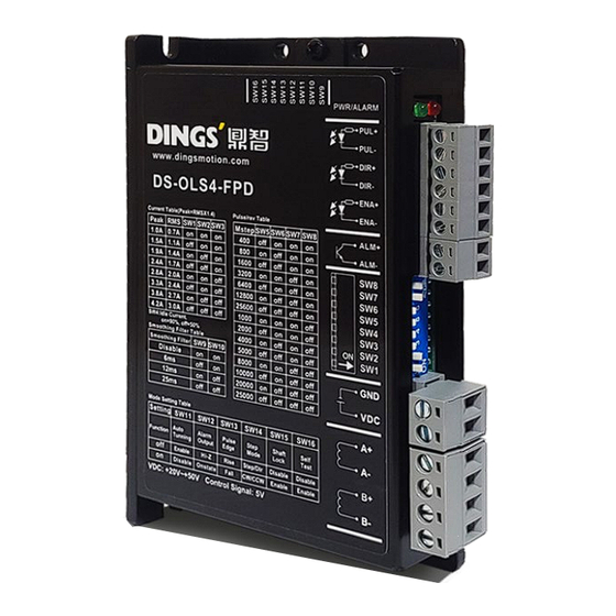
Exquisite design, low noise, and low vibration 1.2 Technical Parameters Drive model DS-OLS4-FPD Adapted to two-phase hybrid stepping motor, Adapter motor DS-OLS4-FPD Maximum adaptation 4.2A Power supply 24 - 48V DC Output current DS-OLS4-FPD:1.0A-4.2A/ phase (peak) Drive mode Full-bridge bipolar PWM driver Dial to select Optocoupler input voltage H = 18-28V, L = 0 - 0.8V... -
Page 4: Dimensional Drawing (Mm)
Introduction 1.3 Dimensional Drawing (mm) Drive installation Install with narrow edges and M4 screws through the holes on both sides. The power device of the driver will generate heat. If it operates continuously under high input voltage and high power conditions, the effective heat dissipation area should be expanded or forced cooling should be applied. -
Page 5: Schematic Diagram And Interface Definition
Schematic Diagram and Interface 2. Schematic Diagram and Interface Definition page | 5... -
Page 6: Set Switch
Set Switch 3. Set Switch Front Dial Current Phase-locked Subdivision setting current setting Side Dial SW10 SW11 SW12 SW13 SW14 SW15 SW16 Band Self tuning Alarm output Pulse edge Single & Double Self check Enable selection selection selection trigger pulse Operation selection selection... -
Page 7: Current Setting
Set Switch 3.2 Current Setting DIP switch Phase current (peak) 1.0A 1.5A 1.9A 2.4A 2.8A 3.3A 3.8A 4.2A 3.3 Filter Setting SW10 Filter setting Default 12ms 25ms (can be set through communication) 3.4 Phase Locked Current Setting SW4=off : (factory default) After the driver stops receiving pulses for about 0.4 seconds, the output current is 50% of the peak value (set to half current, which can reduce the heating of the driver and motor in some applications) SW4=on : The output current of the driver is 90% of the peak value when the motor is stationary. -
Page 8: Pulse Trigger Edge Setting
Set Switch SW12=on : Under normal working conditions, the alarm output is in a high resistance state (non conductive state). When the driver alarms, the alarm output is in a low resistance state (conductive state). 3.7 Pulse Trigger Edge Setting SW13=off : The rising edge of the pulse is valid (factory default) SW13=on : The pulse falling edge is effective. -
Page 9: Power Supply
Power Supply 4. Power Supply 4.1 Voltage The chopper driver continuously changes the magnitude and direction of the motor winding terminal voltage during operation, while detecting the current to obtain accurate phase current. If both high efficiency and low noise are to be ensured, the driver supply voltage should be at least 5 times the rated phase voltage of the motor (the rated phase current of the motor ×... -
Page 10: Motor Connection
Motor Connection 5. Motor Connection When connecting the motor to the drive, please confirm that the power supply to the drive is turned off first. Confirm that the unused motor Caution leads are not shorted to other objects. During the power on period of the driver, the motor cannot be disconnected. -
Page 11: Signal Input
Motor Connection / Signal Input 1) The corresponding colors of different motors are different. When using the motors, the specifications of the motors shall prevail. 2) The windings of different phases of the motor cannot be connected to the terminals of the same phase of the driver (A+, A - represents one phase, B+, B - Notes represents another phase). -
Page 12: Pulse / Direction Input Timing Diagram
Signal Input 6.3 Pulse / Direction Input Timing Diagram Input signal waveform and timing (single pulse method) Input port Input port Input signal waveform and timing (double pulse method) Input port (Forword rotation) Input port (Reverse) Offline Signal : ENA It can accept 5-24VDC single ended or differential signals. -
Page 13: Typical Signal Connection Method
Typical Signal Connection Method 7. Typical Signal Connection Method 7.1 Differential Connection Method PUL+ PUL+ PUL- PUL- DI R+ DI R+ Controller Drive DI R- DI R- ENA+ ENA+ ENA- ENA- 7.2 Co Positive Connection Method PUL+ PUL- DIR+ Drive Controller DIR- ENA+... - Page 14 Typical Signal Connection Method Typical Connection Method for Signal Output Relay Connection ALM / BRK ALM / BRK When the relay is connected, it is required to connect diodes at both ends of the relay Notes (such as IN4000 series) Optocoupler Connection ALM / BRK ALM / BRK...
-
Page 15: Wiring Requirements
Wiring Requirements 8. Wiring Requirements 1) In order to prevent the driver from being disturbed, it is recommended to use shielded cable for the control signal, and the shield layer should be shorted to the ground. Except for special requirements, the shielded wire of the control signal cable is grounded at one end: the upper end of the shielded cable is grounded The driver end of the wire is left floating. - Page 16 International Customer Person in Charge : Daniel Jang daniel@dingsmotion.com No. 2850 Luheng Road, Changzhou Economic Development Zone, Jiangsu Province, China +86-519-85177825, 85177826 North America Customer Person in Charge : Nicolas Ha sales@dingsmotionusa.com 335 Cochrane Circle Morgan Hill, CA 95037 +1-408-612-4970 China +86-0519-8517 7825 Customer...
Need help?
Do you have a question about the DS-OLS4-FPD and is the answer not in the manual?
Questions and answers