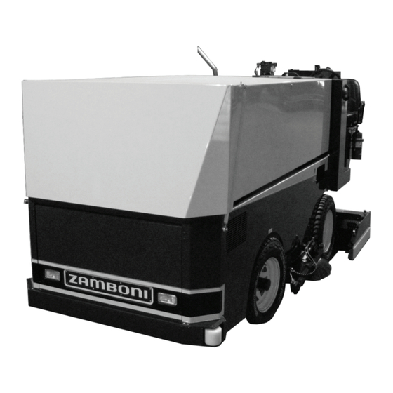

Summary of Contents for Zamboni 445
- Page 1 445 OPERATING INSTRUCTIONS This manual must be kept and stored with the vehicle at all times.
-
Page 3: Table Of Contents
Propane (LPG) Tank Storage and Handling CNG Fuel System Oils Batteries Lubricants Lines, Tubes and Hoses Safe Operation 1-10 Mounting and Dismounting 1-10 Before Operating the Zamboni machine 1-10 Operation 1-10 Parking 1-11 Maintenance 1-12 Walk-Around Inspection 1-12 Battery Operation and Maintenance... - Page 4 Contents Starting the Engine Stopping the Engine Machine Not in Use Travel on Highways 3 Safe Operation 4 Ice Rink Air Quality Adequate Ventilation Air Quality Monitoring Engine Emission System Components Engine Control Unit (ECU) Open Loop versus Closed Loop Operation Oxygen Sensor Catalytic Converter Engine Ignition Timing...
- Page 5 Contents Accelerator Foot Pedal Throttle Switch and Hydrostatic Transmission Control Levers Resurfacing Procedures Learning to Resurface Before Going to the Ice On the Ice Shaving or Cutting Reversible Vertical Auger Operation Typical Resurfacing Operation Using the Snow Breaker Washing the Ice Ice Making Water 7-10 Using the Board Brush...
- Page 6 Contents Emergency Hydrostatic Bypass Valve 10-2 Vertical Auger Hydraulic Stop 10-3 11 Storage Information 11-1 Storage Room Information 11-1 Summer Storage Tips 11-1...
-
Page 7: Introduction
We thank you for choosing a ZAMBONI® product and want to assure you of our continuing interest in your satisfaction with your ice resurfacer. -
Page 8: Safety Symbols
Safety Symbols Safety Symbols Safety Symbols The safety symbols listed outline basic safety precautions. READ AND UNDERSTAND ALL SAFETY PRECAUTIONS AND WARNINGS BEFORE OPERATING, OR PERFORMING LUBRICATION AND MAINTENANCE. Personal Safety These symbols indicate when your safety or the safety of others may be at risk. DANGER! This safety symbol warns of possible personal injury or death. -
Page 9: Ice Resurfacer Guards
Ice Resurfacer Guards Ice Resurfacer Guards The safety guards used on the Zamboni ice resurfacer are illustrated in Figures 1.1 and 1.2. Vertical Auger Coupling Guard Propane Tank Strap & Buckle Chain and Pulley Guard, Conditioner Covers Horizontal Auger (not shown) - Page 10 Ice Resurfacer Guards Snow Tank Safety Stand Figure 1.2 Ice Resurfacer Guards - Snow Tank Safety Stand viii...
-
Page 11: Zamboni Ice Resurfacer Specifications
Zamboni® Ice Resurfacer Specifications Zamboni Ice Resurfacer ® Specifications GM 3.0 Litre L4 Fuel Types: Gasoline, Propane (LPG), Natural Gas (CNG). Available as dual fuel (Gasoline / Propane, Engine Natural Gas / Propane) or dedicated fuel. Load sensing electronic governor enables true “hands- free”... -
Page 12: Dimensions
Zamboni® Ice Resurfacer Specifications Tank Capacities Snow Tank Actual 2.66 m (94 ft Compacted 3.17 m (112 ft Ice Making Water 627 L 166 USG 138 IMP GAL Wash Water (opt.) 218 L 58 USG 48 IMP GAL Total 845 L... - Page 13 Zamboni® Ice Resurfacer Specifications Dimensions...
-
Page 14: Foreword
It is mandatory that all operators review in detail this manual before performing any operation. • Read - understand - and keep this manual with the Zamboni ice resurfacer. • Some illustrations show details or attachments that may be different from your machine. -
Page 15: General Safety Practices
Please refer to your provincial Health and Safety regulatory body for a complete list of rules and regulations. Regulations vary from province to province as well as country to country; operate your Zamboni ice resurfacer in accordance with local regulations. - Page 16 General Safety Practices It is the responsibility of the owner to perform a job safety analysis of all hazards associated with the total environment in which the Zamboni machine will operate and to train all personnel annually. The warnings in the manual and on the machine are identified by the symbols:...
-
Page 17: Warning Signs And Labels
Please obtain the most current information from your local distributor or the Zamboni factory before starting any job. For a list of the most current publications please contact: Zamboni Company Ltd., 38 Morton Avenue East, P.O. Box 1388, Brantford, Ontario, Canada N3T 5T6 (519) 758-5000 Warning Signs and Labels There are several specific safety signs on your Zamboni machine. -
Page 18: Crushing Or Cutting Prevention
General Safety Practices • Do not allow anyone to stand or pass under the elevated portion of any machine. • Be sure operating surface can safely support machine. • Observe safety rules when handling fuel on engine powered machines and when changing or charging batteries for electric machines. - Page 19 Never use a match or open flame to check for leaks, use a soap solution. • Always close the LPG tank service valve, remove the tank(s) and store them in an outside, locked cage when the Zamboni machine is parked for the night or for any extended length of time. •...
-
Page 20: Propane (Lpg) Tank Storage And Handling
Only properly trained and designated persons should charge or exchange the LP gas tanks. • The engine should be stopped and no persons should be on the Zamboni machine during refueling. • Always install tanks and make tank connections outdoors or in a well ventilated area away from heat, ignition sources and open flames. -
Page 21: Cng Fuel System
Never use a match or open flame to check for leaks, use a soap solution. • Always close the LPG tank service valve, remove the tank(s) and store them in an outside, locked cage when the Zamboni machine is parked for the night or for any extended length of time. CNG Fuel System The installation of distribution, storage and dispensing (charging) systems must be done in accordance with the ANSI/IAS NGV4.1-1999 / CSA 12.5-M99 (R04) and any other... -
Page 22: Oils
Do not smoke in areas where batteries are charged or where flammable materials are stored. • Clean and tighten all electrical connections. Check daily for loose or frayed electrical wires. Have all loose or frayed electrical wires tightened, repaired or replaced before operating the Zamboni ice resurfacer. 1 - 8... -
Page 23: Lubricants
• Repair any loose or damaged oil lines, tubes and hoses. Leaks can cause fires. Contact the Zamboni Company or your Zamboni machine dealer for repair or replacement. • Check lines, tubes and hoses carefully. Do not use your bare hand to check for leaks. -
Page 24: Safe Operation
Use extra care when wet or slippery conditions exist. • Never get on or off a moving Zamboni machine. Never jump off the machine. • Do not try to climb on or off the ice resurfacer when carrying tools or supplies. -
Page 25: Parking
General Safety Practices Parking • Park the Zamboni machine in authorized areas only. • Remove foot from the acceleration foot pedal to place the machine in NEUTRAL. • Lower the conditioner onto blocks. • Turn the key switch OFF and remove the key. -
Page 26: Maintenance
Maintenance Walk-Around Inspection For maintenance and operator personnel safety and maximum service life of the Zamboni machine, make a thorough walk-around inspection when doing lubrication and maintenance work. Look around and under for such items as loose or missing bolts, trash or dirt build- up, oil leaks and cut or gouged tires. - Page 27 General Safety Practices • Lower the conditioner or other implements to the ground before performing any work on the machine. • Use steps and grab handles (if applicable) when mounting or dismounting a machine. Clean any mud or debris from steps, walkways or work platforms before using.
- Page 28 Caution should be used to avoid breathing dust that may be generated when handling components containing asbestos fibers. If this dust is inhaled, it can be hazardous to your health. Components in Zamboni machine products that may contain asbestos fibers are brake pads, brake band and lining assemblies, and some gaskets.
-
Page 29: Battery Operation And Maintenance
General Safety Practices • Use exhaust ventilation on permanent machining jobs. • Wear an approved respirator if there is no other way to control the dust. • Comply with applicable rules and regulations for the work place (for example in the U.S.A., OSHA requirements as set forth in a 29 CFR 1910.1001) •... - Page 30 Cold Storage Applications When a Zamboni machine is operated in very cold applications at temperatures as low as -4 degrees Fahrenheit (-20 degrees Celsius), the battery capacity is decreased. Operation at cold temperatures can also cause mechanical failures, short circuits and too much wear due to the formation of ice crystals.
-
Page 31: General Operating And Maintenance Information
“break-in” period. Service schedules for machine lubrication and preventative maintenance have been established on the basis of hourly, daily, weekly and monthly intervals (see 445 Service Manual). Along with performing regular machine lubrication and preventative maintenance according to these schedules, it is advised that you have the ice resurfacer and its components completely checked over periodically by a competent mechanic. -
Page 32: Starting The Engine
General Operating and Maintenance Information Fuel Recommendation This engine is designed to operate on unleaded 87 or 89 octane gasoline. The engine, with the proper fuel equipment, can also be operated on dry fuel such as LPG and NG. NOTE: It is highly recommended that a fuel stabilizer additive be used for any length of storage. -
Page 33: Stopping The Engine
General Operating and Maintenance Information Stopping the Engine To stop the engine: • Return the acceleration foot pedal to Neutral. Set the parking brake, if so equipped. • Return the auger control levers to Off/Neutral. • After the snow tank has been emptied, lower the conditioner onto blocks. Lower the engine RPM to idle by using the engine speed switch. -
Page 34: Travel On Highways
General Operating and Maintenance Information Travel on Highways The machine is not designed for highway use. Fast driving on the highway and bouncing the vehicle over bumps can seriously damage the machine. Travel over extended distances should be avoided, if possible. If such travel is required: •... -
Page 35: Safe Operation
Safe Operation Safe Operation Your Zamboni ice resurfacer is the result of many years of experience in the ice resurfacing field. The engineering and safety features that have gone into your Zamboni machine will be enhanced by you, the safe operator... - Page 36 Safe Operation DANGER! Turn off and remove the ignition key before adjusting, repairing, cleaning, or servicing the conveyors. The vertical and horizontal augers will continue to rotate for a short period of time after the auger control valves have been shut off. Always allow for all auger rotation to stop before working near or on the augers.
- Page 37 Safe Operation DANGER! Internal combustion engines produce exhaust emissions that contain dangerous gases, including carbon monoxide (CO) and nitrogen dioxide (NO These gases can cause serious injury or death. The rink MUST be adequately ventilated during every operation of the ice resurfacer. Also the resurfacer must be kept properly maintained and serviced at all times and the engine timing should always be properly set.
-
Page 39: Ice Rink Air Quality
Ice Rink Air Quality Ice Rink Air Quality In order for a rink to have the best air quality possible, the Zamboni machine must be operated properly in a rink that: • Is adequately ventilated. • Performs daily air quality monitoring/measuring. -
Page 40: Engine Emission System Components
Ice Rink Air Quality The arena's ventilation system can also dramatically affect the indoor air quality by: • Not being properly operated. • Not being properly maintained. • Not being properly designed such as: • Inadequate size or performance. • Intake air systems drawing in air from other polluted areas, such as a vehicle parking lot or garage. -
Page 41: Engine Control Unit (Ecu)
Ice Rink Air Quality Engine Control Unit (ECU) The ECU works to control the engine's air-fuel ratio (AFR) to the ideal levels based on the engine's operating conditions. The ECU monitors the engine for speed, load, air and coolant temperature and then adjusts the AFR via the electronic fuel injection to produce the ideal mixture. -
Page 42: Oxygen Sensor
The oxygen sensor must be replaced every 1500 hours of operation. Catalytic Converter Your Zamboni ice resurfacer is equipped with a “three-way” catalytic convertor. The catalytic convertor is designed to reduce the amount of certain exhaust gases. A three way catalytic... -
Page 43: Engine And State Of Tune
Ice Rink Air Quality Engine and State of Tune The engine’s condition and state of tune refer to how the engine is operating and whether the operating variables of the engine have been adjusted to provide optimal performance. An engine tune-up includes: •... -
Page 44: Engine Emission Systems
Ice Rink Air Quality Engine Emission Systems - Inspection and Maintenance DANGER! Internal combustion engines produce exhaust emissions that contain dangerous gases, including carbon monoxide (CO) and nitrogen dioxide (NO ). These gases can cause serious injury or death. The rink MUST be adequately ventilated during every operation of the ice resurfacer. -
Page 45: Inspection And Maintenance Chart
Ice Rink Air Quality Engine Emission System - Inspection and Maintenance Chart Serial No.: Fuel Type: Catalytic Converter Type: ____________________ _____________________ ______________________ Date By Hours Engine Cond. After Catalytic Converter Levels OK compared to previous testing? Idle Load Idle Load Idle Load Idle... -
Page 46: Recommended Maintenance Schedule
Ice Rink Air Quality Recommended Maintenance Schedule GASOLINE AND LPG CERTIFIED ENGINE MAINTENANCE REQUIREMENTS Interval Hours Install Date Daily 1000 1250 1500 1750 2000 General Maintenance Section Visual Check for Leaks Check Engine Oil Level Check Coolant Level Change Engine Oil and Filter Every 150 Hours or 120 Days of Operation Check LPG/Gas System for Leaks Prior to any Service or Maintenance Activity... -
Page 47: Ice Resurfacer Components
Ice Resurfacer Components Ice Resurfacer Components Front View Snow Tank Lid Snow Tank Engine Compartment Board Brush Access Door (Option) Guide Wheel Horizontal Auger Conditioner Figure 5.1 Ice Resurfacer Components (front view) 5 - 1... -
Page 48: Rear View
Ice Resurfacer Components Rear View Propane Tank Vertical Auger Drive Exhaust Pipe Strap & Buckle LPG Tank Trays Conditioner Chain Guard Conditioner Ice Making Water Squeegee Distribution Pipe Figure 5.2 Ice Resurfacer Components (Rear View) 5 - 2... -
Page 49: Operator's Platform
Ice Resurfacer Components Operator's Platform Ice Making Wash Water Wash Water Tank Instrument Panel Water Control Control Snow Breaker Blade Adjustment Wheel Snow Tank Control Auger Control Conditioner Lift Figure 5.3 Ice Resurfacer Components - Operator's Platform 5 - 3... - Page 50 Ice Resurfacer Components Power Package (Engine) Electronic Pressure Regulator (EPR) / Oil Dipstick Radiator Fan Vaporizer Flywheel Housing Auxiliary Pump Starter Motor Oil Filter Hydrostatic Engine Controller (ECU) Exhaust Pipe (Drive) Pump Radiator Air Cleaner Alternator Figure 5.5 Ice Resurfacer Components - Power Package 5 - 4...
-
Page 51: Snow Tank Safety Stand
Ice Resurfacer Components Snow Tank Safety Stand Ice Making Water Tank Figure 5.6 Ice Resurfacer Components - Snow Tank Safety Stand 5 - 5... -
Page 53: Operator's Station
Operator's Station Operator's Station INSTRUMENT PANEL GAUGES WARNING LIGHTS CONTROL SWITCHES Figure 6.1 Operator Area 6 - 1... -
Page 54: Tachometer/Hourmeter
Operator's Station Horn Ice Making Water Level Gauge (Option) Lights Tachometer / 4-in-1 / 3-in-1 Hour Meter Gauge Wash Water Pump (Option) Malfunction Indicator Board Brush Light (MIL) Fuel Selector Switch Tire Wash (option) CNG / Alternator Light Snow Breaker Manual Override Oil Pressure Light Engine Temperature Light... -
Page 55: Warning Lights, Buzzers, "Limp Home" And
Alternator voltage, alternator output Malfunction Indicator Light See fault codes (MIL) In all cases, if you are unsure of the cause and remedy for a warning lamp or buzzer, please contact the Zamboni Company for more information. 6 - 3... - Page 56 Operator's Station Engine Oil Pressure If the engine oil pressure is low (between 4 and 7 psi), the ECM will take the following action: • Turn on the malfunction indicator light. • Turn on the low oil pressure light. • Shut the engine down after 30 seconds.
-
Page 57: Machine Operation Switches
Operator's Station The operator can cycle the key off and then restart the engine. If the temperature is still above 235°F it will again shut the engine off after 60 seconds. This will allow the operator to get the machine off of the ice. Check the coolant level in the radiator when it is safe to do so. -
Page 59: Operating The Ice Resurfacer
Vehicle Controls The Zamboni ice resurfacer has familiar automobile-style driving controls. The ice resurfacer is steered with the steering wheel. It has two foot pedals, one that controls the direction and acceleration and the other one is a brake pedal. It has a hydrostatic transmission that allows for smooth operation. -
Page 60: Hydrostatic Transmission
The electronic governor maintains the engine RPM independent of the load of the engine. See your 445 Service Manual for more details on the electronic governor. When resurfacing, the engine speed should be set between 2200 and 2500 RPM. The operator must not "lug"... -
Page 61: Throttle Switch And
Operating the Ice Resurfacer Throttle Switch and Hydrostatic Transmission Control Throttle Rocker Switch Brake Pedal Accelerator Foot Pedal Figure 7.1 Motion Controls Figure 7.2 Direction Decal 7 - 3... -
Page 62: Resurfacing Procedures
You will produce higher quality ice if you read, understand and practice the following information. Historically, the best sheet of ice produced prior to the development of the Zamboni ice resurfacer was usually produced by the following procedures: •... -
Page 63: Learning To Resurface
Operating the Ice Resurfacer Learning to Resurface Before Going to the Ice • Check the water level in the water tanks. • The blade must be level (see Figure 9.5) and at the correct angle (see Figure 9.6). • The conditioner must be raised completely. •... -
Page 64: Shaving Or Cutting
Operating the Ice Resurfacer Shaving or Cutting • Proceed from the storage area onto the ice (see Figure 7.4). • When starting the resurfacing pattern, it is recommended to start down the center of the ice surface so the functions can be started and blade adjustments can be made at some distance from the walls or boards. - Page 65 Operating the Ice Resurfacer (Optional) Reversible Vertical Auger Operating Instructions The vertical auger is equipped to rotate in both directions. The normal rotation for resurfacing is FORWARD, as shown by the information decal located near the valve operating handle. Note: Since the vertical and horizontal augers are hydraulically connected in series, both augers will rotate in the reverse direction if the optional reverse auger funtion is enabled.
-
Page 66: Typical Resurfacing Operation
Operating the Ice Resurfacer Typical Resurfacing Operation Figure 7.4 Going onto the Ice Figure 7.5 Leaving the Ice 7 - 8... -
Page 67: Using The Snow Breaker
Operating the Ice Resurfacer Using the Snow Breaker The operator should use the snow breaker several times a minute (or more as required). The snow breaker helps remove snow or ice that will build up in the corners of vertical auger opening. -
Page 68: Ice Making Water
Operating the Ice Resurfacer Ice Making Water Using hot water for the ice making water will generally produce the best ice surface. Do not use water hotter than 160 F (70 C) as this could damage the plastic ice making water tank. To use the ice making water during a resurfacing: •... -
Page 69: Removing Excess Water From The Ice
Operating the Ice Resurfacer • After a complete lap of the ice surface next to the boards, retract the board brush by turning off the board brush switch. This will also stop the brush motor. • Proceed with the other resurfacing operations over the remainder of the ice surface. -
Page 70: Removing Slush From The Ice
Note: Whenever excess water or slush is being removed from the ice surface and conveyed into the snow tank, the Zamboni ice resurfacer ice making water tank must be empty. Water in both the ice making water tank and the snow tank may load the machine excessively. -
Page 71: Leaving The Ice Surface
Operating the Ice Resurfacer Leaving the Ice Surface When leaving the ice surface after finishing a resurfacing (or any other time): (See Figure 7.5) • Close the wash water system valve. Turn off water pump (if used). • Turn off the auto snow breaker (if equipped). •... -
Page 72: Operating Pointers
Operating the Ice Resurfacer Operating Pointers Resurfacing Patterns The following diagram shows a good resurfacing pattern: Figure 7.6 Standard Resurfacing Pattern Sharp Turns The ice resurfacer has a power steering system which contains a hydraulic relief valve. This valve only operates when the wheels are jammed up against an object or when the operator turns the steering wheel completely to the left or the right and holds it there against the stop. -
Page 73: Excessive Loads
Operating the Ice Resurfacer Excessive Loads Taking too deep a cut with the shaving blade while driving the machine at it's full ground speed may place an excessive load on the engine. The engine RPM is maintained with only a small RPM drop while resurfacing normally. With an excessive machine load, the engine RPM may drop excessively which will cause the operation of the machine to suffer. -
Page 75: Water System
Water System Water System A. Pipe A (Figure 8.2) supplies water from the wash water tank to the conditioner. B. Hose B (Figure 8.1) carries water picked up in the conditioner, via pipe B, from the water pump back to the wash water tank. The water flows through the filtering screen at which point the water can be recirculated. - Page 76 Water System Wash Water Transfer Valve (D) Optional Wash Water Pipe (A) Ice Making Water Pipe (C) Pipe (B) Wash Water Distribution Pipe Blade Adjustment Screw & Greasable Clevis Wash Water Pickup (Suction) Wash Water Outlet (Both Ends Of Conditioner) Figure 8.2 Conditioner Underside 8 - 2...
- Page 77 Water System Ice Making Water Ice Making Water Fill Tank Cover Overflow Discharge Ice Making Water Tank Figure 8.3 Ice Making Water System Wash Water Return Wash Water Screen Wash Water Tank Cover Figure 8.4 Wash Water System 8 - 3...
-
Page 79: Maintaining The Cutting Blade
Maintaining the Cutting Blade Maintaining the Cutting Blade It is essential that the blade be sharp if the resurfacer is to operate properly. Conditions vary from one rink to another, but experience has shown that normally the cutting blade is dull and needs re sharpening after 5 to 7 days of operations. -
Page 80: Used Blade
Maintaining the Cutting Blade Used Blade Use REAR mounting holes when blade is 4" wide or less. Note: Hardened material is exhausted when blade is approximately 3" wide. Discard blade. Blade Controls on Conditioner Blade Height Adjusting Screws level each side of the blade in relation to the runners. Side Controls Down Blade Height... -
Page 81: Hand Wheel
Maintaining the Cutting Blade Hand Wheel The center hand wheel control varies the angle of the blade. If the blade is level with each runner, the hand wheel will make uniform changes in depth of cut. Centre Hand Wheel Down Side View Conditioner Runner Blade... -
Page 82: Holding And Securing The Blade
Maintaining the Cutting Blade Holding and Securing the Blade Blade Holding Bar (5K-78890) Blade (5K-33630) Bolt Tightening Sequence Blade Holding Bar Blade 0.08" Machined Surface on Blade Holding Bar Blade Figure 9.4 Blade Holding Bar The ends of blade holding bar are machined upward approximately 0.08" so that one cut of the ice is feathered into the adjoining cut. -
Page 83: Procedure For Setting Blade Angle And Depth Of Cut
Maintaining the Cutting Blade Procedure for Setting Blade Angle and Depth of Cut Step 1: Set blade at approximately 10 angle as shown on the blade angle adjusting plate (Figure 9.6) by rotating center hand wheel control. Step 2: Align leading edge of blade EVEN with BOTH conditioner runners. It is quite helpful to use a flat washer, a large coin or the blade adjusting tool (Part No. - Page 84 Maintaining the Cutting Blade Blade Angle Adjustment Decal A blade angle decal is located on the inside of the conditioner left side plate (see Figure 9.6). When the blade holding bar is lined up, parallel to the series of lines, the blade angle is approximately 10 °...
-
Page 85: Conditioner Down Pressure
Maintaining the Cutting Blade Conditioner Down Pressure The purpose of the conditioner down pressure system is to create downward pressure on the shaving blade thus increasing the shaving capability of the machine. Down Pressure Spring Adjustment Procedure • Lift Conditioner slightly off of the ground, just so it clears the floor. •... -
Page 86: Using The Edger
Zamboni Power Edger ® Walk around boards as required to reduce edge. After edging, use Zamboni ® machine next to boards and complete resurfacing pattern Figure 9.8 Zamboni Edger 9 - 8... -
Page 87: Edger Attachment
Maintaining the Cutting Blade Edger Attachment Mount the edger on the driver's side of the conditioner and bolt tightly at the three locations shown below. The depth of cut on the edger blade may be adjusted by turning the two blade adjustment set screws. -
Page 89: Emergency Operation Emergency Hand Pump
Emergency Operation Emergency Operation Emergency Hand Pump The emergency hand pump is located in the driver area of the machine. The pump handle must be stored where the operator can find it in an emergency. Purpose: The emergency hand pump is used to raise the conditioner or the snow tank in the event the engine will not operate. - Page 90 Emergency Operation Emergency Hydrostatic Bypass Valve Should it be necessary to move the machine when the engine is not operable, the emergency bypass valve, located on the hydrostatic pump, must be opened (see Figure 10.3). This valve is located on the hydrostatic pump and painted red for ease of identification, in the engine compartment.
- Page 91 Emergency Operation VERTICAL AUGER HYDRAULIC STOP The Zamboni Company Ltd. Model 445 Ice Resurfacing Machines are now equipped with a vertical auger hydraulic stop valve. The valve is controlled by a normally open electrical switch located near the front of the snow tank.
- Page 92 Storage Information Storage Information Storage Room Information Storage Area Due to the great amount of water associated with this machine, it should be stored between resurfacing in a room heated above freezing. The room should be as close to the edge of the rink as possible and the surfaces between the storage area and the rink should be paved so dirt will not be tracked onto the ice.
- Page 93 38 Morton Ave. East, Box 1388, Brantford, ON Canada N3T 5T6 Phone (519) 758-5000 Fax (519) 758-0500 ZAMBONI and the configuration of the Zamboni ice resurfacer ® are registered trademarks of Frank J. Zamboni & Co., Inc. www.zamboni.com Part Number DM-20066...
- Page 94 PARTS LIST Your machine's updated parts list is available online at Zamboni.com in the Owners Area and Resource Center...
Need help?
Do you have a question about the 445 and is the answer not in the manual?
Questions and answers
не крутиться шнек
The auger may not be turning because the snow tank is up. The system is designed so that the solenoid valve is only powered when the snow tank is in the down (operating) position. If the tank is up, the solenoid valve is not powered, which prevents the auger from operating.
This answer is automatically generated