Table of Contents
Advertisement
Quick Links
Advertisement
Table of Contents

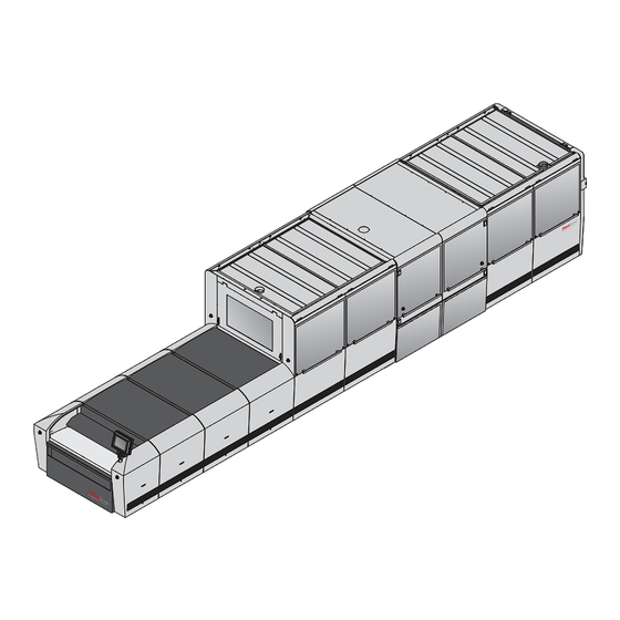
Summary of Contents for Flint nyloflex IRIS Inliner
- Page 1 Pre-installation Manual nyloflex ® IRIS Inliner...
- Page 3 Pre-installation Manual nyloflex ® IRIS Inliner T11453 Edition AA, September 2015 This book has part No 10081320...
- Page 4 This manual is published by: Glunz & Jensen S.p.A. Via Alessandro Volta 28 20088 – Rosate (MI) – ITALY Tel.: +39 02 900 90 180 – Fax: +39 02 900 90 149 Internet: www.degraf.glunz-jensen.com Copyright © 2015 by Glunz & Jensen S.p.A. Pre-installation Manual - nyloflex®...
-
Page 5: Part 0: Introduction
Introduction Part 0: Introduction Reservations This manual was written and illustrated using the best possible information • available at the time of publication. Any differences between this manual and the equipment reflect improvements • introduced after the publication of the manual. Changes, technical inaccuracies and typographic errors will be corrected in •... -
Page 6: Table Of Contents
Introduction Table of contents Table of contents Part 0: Introduction ........0-3 Reservations . -
Page 7: Part 1: Transportation
Transportation When the equipment arrives Part 1: Transportation When the equipment arrives Storing the equipment before installation The crated equipment (4 crates) will usually be delivered some time before the arrival of the Service Technician. In which case you should prepare an appropriate place indoors to store the crated equipment. -
Page 8: Dimensions And Weight
Transportation The crate Dimensions and weight T32977 Processor Tower 1 Elevator Tower 2 Width (W) 2320 mm 2300 mm 2300 mm 2300 mm (91.3") (90.6") (90.6") (90.6") Length (L) 4380 m 2720 mm 2270 mm 2570 mm (172.4") (107.1") (89.7") (101.2") Height (H) 1440 mm... -
Page 9: Transporting The Equipment
Transportation Transporting the equipment Transporting the equipment Lifting the crate The equipment is supplied in a wooden crate. The equipment is very heavy equipment. To lift the crate a fork-lift truck is required. T32327 Available width for transport Depending on the width of the door(s) through which the equipment has to be transported to the installation site, the Service Technician may have to perform the actions described in the table below: If width of the door is…... - Page 10 Transportation Transporting the equipment Pre-installation Manual - nyloflex® IRIS Inliner 1536...
-
Page 11: Part 2: Installation Requirements
Installation requirements Environmental requirements Part 2: Installation requirements This equipment must be installed in restricted access locations only. Environmental requirements Provide a heating and ventilation system capable of maintaining room temperature between 17 and 25°C (63 and 77°F) and relative humidity between 40 and 60%. For heat emission see "Power consumption"... -
Page 12: Space Requirements
Installation requirements Space requirements Space requirements Free space around the equipment Decide where the equipment shall be placed and make sure that the free space around the equipment makes servicing possible. The recommended minimum free space around the equipment is: 2500 mm (98.4") in front and at the back of the equipment, •... -
Page 13: Equipment Dimensions
Installation requirements Space requirements Equipment dimensions " ) T11452 1536 Pre-installation Manual - nyloflex® IRIS Inliner... -
Page 14: Connection Locations
Installation requirements Space requirements Connection locations " ) " ) T33448 Compressed air supply The compressed air supply connection is located on the rear side of the equipment. The supply air pressure must be min. 6 bar (87 psi) and max. 10 bar (145 psi). The required compressed air volume is min. -
Page 15: Electrical Requirements
Installation requirements Electrical requirements Exhaust All the exhausts must be connected to the appropriate location (directly to the outside or to the building exhaust installation). Make sure that the airflow is correct. Minimum exhaust of the equipment is 1800 m Electrical requirements Electrical installation must conform to local regulations and guidelines. -
Page 16: Electrical Specifications
Installation requirements Electrical requirements Electrical specifications Installation requirements for power supply Supply / fuse Recommended cable type 3Ph + N + PE, 400 VAC Min. 5 x 16 mm 3 x 60 Amps, 50-60 Hz type H07RNF Voltage tolerance ± 10% Fuses The fuses must have a breaking capacity of min. -
Page 17: Part 3: Pre-Installation Checklist
Pre-installation checklist Part 3: Pre-installation checklist Please ask the customer to answer the following questions in order to ensure a trouble-free installation of the equipment: 1. Delivery of the crate and transport to the installation site YES NO A. Is there a place indoor where the crated equipment can be stored temporarily? B. - Page 18 Pre-installation checklist 3. Connections YES NO A. Capacity of air condition/ventilation adequate with regard to power consumption as specified on pages 2-1 and 2-6? B. Is there a compressed air supply available? C. Can a hose (6 mm diameter) be connected to the compressed air supply? D.
Need help?
Do you have a question about the nyloflex IRIS Inliner and is the answer not in the manual?
Questions and answers