Advertisement
Quick Links
Thank you for using EXPERT Compact inverter manufactured by Himel
This series inverter is a general-purpose frequency converter based on flux
vector algorithm control. It has a series of practical functions such as motor
parameter self-identification, big torque at low frequency, wobble frequency
control, droop control, simple PLC, fixed length control and flexible frequency set
mode, and can achieve a variety of frequency combinations setting and RS485
communication.
Before using the inverter, the inverter user and the relevant technicians shall
read the User Manual carefully to ensure the correct installation and operation of
the inverter and its optimal performance.
The User Manual is subject to change without prior notice. The new edition
shall prevail.
High performance general vector frequency inverter
User Manual
Edition Code: V1.0
EXPERT Compact Series User Manual
Preface
1
Advertisement

Summary of Contents for Himel EXPERT HAV-XC-2S0004G
- Page 1 EXPERT Compact Series User Manual Preface Thank you for using EXPERT Compact inverter manufactured by Himel This series inverter is a general-purpose frequency converter based on flux vector algorithm control. It has a series of practical functions such as motor...
- Page 2 EXPERT Compact Series User Manual Chapter 1 Product specifications and ordering instructions 1.1 frequency inverter series model. Model description HAV - 0015 (-S) Inverter Series S: Floor standing B: BASIC S: SMART Voltage Class Inverter Type X: EXPERT 2: 220V G: Constant Torque 4: 380V-440V P: Variable torque Pump...
- Page 3 EXPERT Compact Series User Manual The frequency inverter has two voltage levels of 220V and 380V, and the power range of the adaptor is 380V: 0.4 kW ~ 4kW. 220V: 0.75 kW to 2.2 kW. The model of this series inverter is shown in table 1-1. Table 1-1 type of inverter.
- Page 4 EXPERT Compact Series User Manual Table 1-2 the shape of the inverter and the installation serial size (unit: mm) Mounting holes Refer Specification W W1 H H1 D D1 straight to figure Diameter (Φ) HAVXC2S0004G HAVXC2S0007G HAVXC2S0015G 75 55 188 177.5 179.5 169 160 HAVXC4T0007G HAVXC4T0015G HAVXC4T0022G...
- Page 5 EXPERT Compact Series User Manual 2. The wiring length of the brake resistance should be less than 5m, and the braking resistance will increase the temperature in the process of energy consumption braking, and the safety protection and ventilation should be paid attention to during installation.
- Page 6 EXPERT Compact Series User Manual Chapter 2 Installation and wiring of frequency inverter. 2.1 installation environment of the inverter. 2.1.1 installation environment requirements. (1) install in a well-ventilated indoor environment, and the ambient temperature requires that in the range of –10ºC~40ºC, if the temperature exceeds 40, the external forced cooling or reduction should be used.
- Page 7 EXPERT Compact Series User Manual 2.1.3 mechanical installation methods and procedures. 1. Forward wall installation control cabinet installation board 2-3 schematic diagram of wall mounting of plastic structure. 2. side wall installation control cabinet installation board 2-4 schematic diagram of wall mounting of plastic structure.
- Page 8 EXPERT Compact Series User Manual 3. DIN-rail installation The rack guide 2-5 schematic diagram of embedded installation of plastic structure. 2.2 frequency inverter panel disassembly and installation 2.2.1 plastic machine box inverter panel remove and install Install cover board According to figure 2-6, the guide bar in the bottom of the cover plate is aimed at the guide slot of the main body, which is to be aligned in one direction, and then push the cover plate in two directions until the "click"...
- Page 9 EXPERT Compact Series User Manual Figure. 2-8 the opening and closing of RJ45 cover. 2.2.2 remove and install of the operation panel. Remove the cover board Press in figure. 2-9, press with your finger in the direction of 1, and then pull out the main body of the machine box and pull out the cover in 2 directions.
- Page 10 EXPERT Compact Series User Manual 2.3.1 wiring of main circuit terminals. (1) the input and output terminals of the main circuit are shown in table 2-1. Applicable model Main circuit terminal Terminal name Function explanation Three phase 380V input R, S, T HAVXC4T0007G Three phase output terminal U, V, W...
- Page 11 EXPERT Compact Series User Manual DI1 DI3 DI5 DO1 DO2 AO1 AI1 485+ 485- 10V 24V Figure 2-11 sequence diagram of terminal of control panel. 2.4.2 CN3 terminal function description, as shown in table 2-3. Table 2-3 control terminal function table. Terminal Terminal function category...
- Page 12 EXPERT Compact Series User Manual Provide analog voltage Voltage output range: Analog Analog output for 12 physical 0 ~ 10V. output output quantities (see Current output range: F6.24/F6.25 for details) 0 ~ 20mA. Multi-function input terminal1 Multi-function input It can be defined as the terminal2 switch quantity input terminal of various...
- Page 13 EXPERT Compact Series User Manual 2.4.3 the wiring of analog input terminal. AI1 and AI2 terminals receive analog signal input and select input voltage (0 ~ 10V) or input current (0 ~ 20mA) through function code F5.12. The terminal line method is shown in figure 2-12: 0~10Vor 0~20mA Inverter...
- Page 14 EXPERT Compact Series User Manual 2.4.5 connection mode of inverter control circuit. Braking resistor The circuit contactor breaker (+) the motor GT100 Analog quantity reference ground Analog output 1 Multi-function terminal 1 Open collector output Multi-function terminal 2 Open collector output (optional Multi-function terminal 3 high speed pulse output) Multi-function terminal 4...
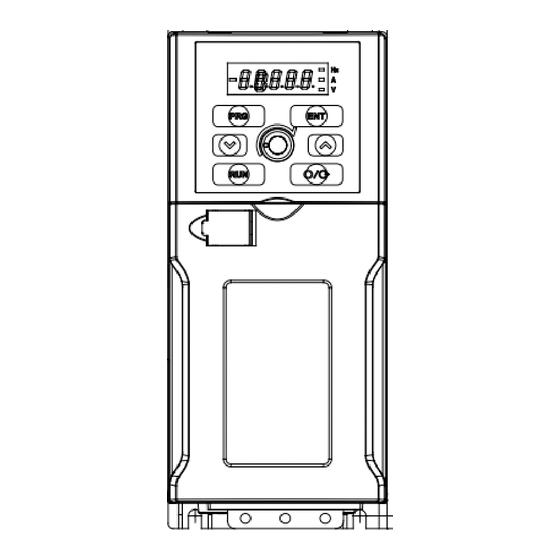
- Page 15 EXPERT Compact Series User Manual Chapter 3 Frequency Inverter’s operation and instruction 3.1 Button function description The frequency converter operation panel is provided with 6 keys, each function definition of the key is shown in table3-1. Table 3-1 operation panel function table Keys Name Icon...
- Page 16 EXPERT Compact Series User Manual 3.2.1 Monitor parameters checking Monitor parameters display switching Press UP key or Down key, display F0.07 status monitor parameter, at the same time the corresponding indicator light is on. Such displaying setting frequency, its unit “Hz”...
- Page 17 EXPERT Compact Series User Manual 3.2.4 Combination key operation Combination key operation is valid only when displaying monitor parameter: 1) PRG key + ▼key: When you press PRG key, at the same time press ▼ key, lock operation panel, exact locking choice and range please refer to the function code FC.31 hundred setting.
- Page 18 EXPERT Compact Series User Manual Chapter 4 Function Parameters 4.1 Symbol Description: ×—means that the parameter cannot be modified during the operation process ○—means that the parameter can be modified during the operation process ●—shows actually detected parameter which cannot be modified *—shows manufacturer retention parameter which is forbidden to modify Function Name &...
- Page 19 EXPERT Compact Series User Manual Function Name & Minimum Set Range Factory Default Modify code Definition Unit LED units digit:first parameter display selection 0: Output frequency (before compensation) 1: Output frequency (after compensation) 2: Setting frequency 3: Output current 4: Output voltage 5: Bus voltage Quick parameters 6: AI1...
- Page 20 EXPERT Compact Series User Manual Function Name & Minimum Set Range Factory Default Modify code Definition Unit F1.04 Reserved F1.05 Reserved Maximum output F1.06 F1.09~550.00Hz 0.01Hz 50.00Hz × frequency Running Upper limiting frequency~lower F1.07 frequency digit 0.01Hz 50.00Hz ○ limiting frequency setting F1.08 Reserved...
- Page 21 EXPERT Compact Series User Manual Function Name & Minimum Set Range Factory Default Modify code Definition Unit V/F voltage value F1.23 F1.21~100.0% 0.1% 75.0% × Running direction 0:Forward F1.24 ○ setting 1:Reversal Carrier frequency F1.25 3~15kHz 1kHz 4kHz ○ setting F1.26 Reserved F1.27...
- Page 22 EXPERT Compact Series User Manual Function Name & Minimum Set Range Factory Default Modify code Definition Unit Stop DC braking F2.10 0.00~10.00s 0.01s 0.00s ○ waiting time Stop DC braking 0.0~150.0% frequency F2.11 0.1% 80.0% ○ current converter rated current Stop DC braking 0.0 (no action) F2.12...
- Page 23 EXPERT Compact Series User Manual Function Name & Minimum Set Range Factory Default Modify code Definition Unit 0:Zero frequency allows Zero frequency operation F2.32 operation allows × 1:zero frequency forbid selection operation Motor parameter F3 group F3.00 Motor poles 2~14 ×...
- Page 24 EXPERT Compact Series User Manual Function Name & Minimum Set Range Factory Default Modify code Definition Unit Speed ring (ASR) F4.01 0~10.00 0.01 2.00 ○ proportional gain Speed ring (ASR) F4.02 0.01~10.00 0.01 ○ integral time Vector motor F4.06 0~50 ○...
- Page 25 EXPERT Compact Series User Manual Function Name & Minimum Set Range Factory Default Modify code Definition Unit Curve 1 minimum given F5.05 0.00~F1.06 0.00Hz ○ corresponding frequency F5.04~100.0% (Specific value between Curve 1 F5.06 maximum given value 1 and 0.1% 100.0% ○...
- Page 26 EXPERT Compact Series User Manual Function Name & Minimum Set Range Factory Default Modify code Definition Unit 0:No function 1:Multistage frequency terminal Multifunction input F6.00 terminal DI1 2:Multistage frequency terminal Function selection 3:Multistage frequency terminal 4:Acceleration and deceleration time terminal 1 5:Acceleration and deceleration time terminal 2 Multifunction input...
- Page 27 EXPERT Compact Series User Manual Function Name & Minimum Set Range Factory Default Modify code Definition Unit 33:Reserved 34:Reserved 35:External stop command (Effective to all the control Multifunction input modes, stop according to the F6.05 terminal DI6 current stop mode) Function selection 36:FWD terminal function 37:REV terminal function...
- Page 28 EXPERT Compact Series User Manual Function Name & Minimum Set Range Factory Default Modify code Definition Unit 0:Inverter running indication (RUN) 1: Frequency arrival signal (FAR) 2:Frequency level detection signal (FDT1) 3:Frequency level detection signal (FDT2) 4: Overload detection signal (OL) 5:Stop for undervoltage block Open collector (LU)
- Page 29 EXPERT Compact Series User Manual Function Name & Minimum Set Range Factory Default Modify code Definition Unit F6.14 FDT1 level 0.00~550.0Hz 0.01Hz 50.00Hz ○ F6.15 FDT1 lag 0.00~550.0Hz 0.01Hz 1.00Hz ○ F6.16 FDT2 level 0.00~550.0Hz 0.01Hz 25.00Hz ○ F6.17 FDT2 lag 0.00~550.0Hz 0.01Hz 1.00Hz...
- Page 30 EXPERT Compact Series User Manual Function Name & Minimum Set Range Factory Default Modify code Definition Unit LED units digit:AO1 bias selection Analog output F6.26 0:0~10V or 0~20mA ○ range selection 1:2~10V or 4~20mA LED tens digit:Reserved F6.27 AO1 output gain 0.0~200.0% 0.1% 100.0%...
- Page 31 EXPERT Compact Series User Manual Function Name & Minimum Set Range Factory Default Modify code Definition Unit Rotational speed F7.08 0~100 × tracking gain KP rotational speed F7.09 tracking integral 1~1000 × time Rotational speed F7.10 tracking 0.1~60.0S 0.1s 6.0s ×...
- Page 32 EXPERT Compact Series User Manual Function Name & Minimum Set Range Factory Default Modify code Definition Unit 0:AI1; 1:AI2; 2:AI1+AI2; Feedback 3:AI1-AI2; F8.02 ○ channel selection 4:MIN(AI1,AI2); 5:MAX(AI1,AI2); 6:Pulse 7:Reserved ; Given channel F8.03 0.001~50.000s 0.01s 0.50s ○ smoothing Feedback F8.04 channel 0.001~50.000s...
- Page 33 EXPERT Compact Series User Manual Function Name & Minimum Set Range Factory Default Modify code Definition Unit 0:Direct action Closed loop 1:Reaction F8.16 regulating × Note:Relation between given characteristic speed and rotate speed F8.17 Reserved Closed loop F8.18 0.00~550.0Hz 0.01Hz 0.00Hz ○...
- Page 34 EXPERT Compact Series User Manual Function Name & Minimum Set Range Factory Default Modify code Definition Unit 0:no closed-loop feedback loss Closed-loop detection feedback lost F8.36 1:closed-loop feedback loss ○ movement detection, stop while detection, selection display fault E20 Process closed 0.0~100% loop feedback F8.37...
- Page 35 EXPERT Compact Series User Manual Function Name & Minimum Set Range Factory Default Modify code Definition Unit Multistage F1.10(lower limit frequency)~ F9.03 0.01Hz 20.00Hz ○ frequency 3 F1.09(upper limit frequency) Multistage F1.10(lower limit frequency)~ F9.04 0.01Hz 30.00Hz ○ frequency 4 F1.09(upper limit frequency) Multistage F1.10(lower limit frequency)~...
- Page 36 EXPERT Compact Series User Manual Function Name & Minimum Set Range Factory Default Modify code Definition Unit LED units digit: 0:Multistage frequency 2(F9.02) 1:Determined by F1.02 function code 2:Multistage closed loop given 2(F8.21) 3:Determined by F8.01 function code LED tens digit: 0:Forward F9.10 Stage 2 setting...
- Page 37 EXPERT Compact Series User Manual Function Name & Minimum Set Range Factory Default Modify code Definition Unit LED units digit: 0:Multistage frequency 4(F9.04) 1:Determined by F1.02 function code 2:Multistage closed loop given 4(F8.23) 3:Determined by F8.01 function code LED tens digit: 0:Forward F9.14 Stage 4 setting...
- Page 38 EXPERT Compact Series User Manual Function Name & Minimum Set Range Factory Default Modify code Definition Unit LED units digit: 0:Multistage frequency 4(F9.04) 1:Determined by F1.02 function code 2:Multistage closed loop given 4(F8.23) 3:Determined by F8.01 function code LED tens digit: 0:Forward F9.18 Stage 6 setting...
- Page 39 EXPERT Compact Series User Manual Function Name & Minimum Set Range Factory Default Modify code Definition Unit F1.10 (Lowest ○ Multistage F9.23 frequency)~F1.09(Highest 0.01Hz 45.00Hz frequency9 frequency) F1.10 (Lowest ○ Multistage F9.24 frequency)~F1.09(Highest 0.01Hz 50.00Hz frequency10 frequency) F1.10 (Lowest Multistage F9.25 frequency)~F1.09(Highest 0.01Hz...
- Page 40 EXPERT Compact Series User Manual Function Name & Minimum Set Range Factory Default Modify code Definition Unit LED units digit: 0 : Multistage frequency 4(F9.24) 1:Determined by F1.02 function code 2:Multistage closed loop given 4(F8.28) 3:Determined by F8.01 function code LED tens digit:...
- Page 41 EXPERT Compact Series User Manual Function Name & Minimum Set Range Factory Default Modify code Definition Unit LED units digit: 0:Multistage frequency 4(F9.26) 1:Determined by F1.02 function code 2:Multistage closed loop given 4(F8.30) 3:Determined by F8.01 function code LED tens digit: 0:Forward F9.36 Stage 11 setting...
- Page 42 EXPERT Compact Series User Manual Function Name & Minimum Set Range Factory Default Modify code Definition Unit LED units digit: 0:Multistage frequency 4(F9.27) 1:Determined by F1.02 function code 2:Multistage closed loop given 4(F8.32) 3:Determined by F8.01 function code LED tens digit: 0:Forward F9.40 Stage 13 setting...
- Page 43 EXPERT Compact Series User Manual Function Name & Minimum Set Range Factory Default Modify code Definition Unit LED units digit: 0:Multistage frequency 4(F9.29) 1:Determined by F1.02 function code 2:Multistage closed loop given 4(F8.34) 3:Determined by F8.01 function code LED tens digit: 0:Forward F9.44 Stage 15 setting...
- Page 44 EXPERT Compact Series User Manual Function Name & Minimum Set Range Factory Default Modify code Definition Unit LED units digit:Action selection 0:Detecting all the time 1:Detect only in constant speed LED tens digit:Alarming selection Overload 0:No alarming, continue to FA.11 pre-alarm ×...
- Page 45 EXPERT Compact Series User Manual Function Name & Minimum Set Range Factory Default Modify code Definition Unit Serial port communication parameter FB group Fb.00 Local address 0-247,0 is broadcast address × LED units digit:Baud rate selection 0:1200BPS 1:2400BPS 2:4800BPS 3:9600BPS 4:19200BPS 5:38400BPS LED tens digit:data format...
- Page 46 EXPERT Compact Series User Manual Function Name & Minimum Set Range Factory Default Modify code Definition Unit Energy Models FC.00 consumption 380-800V × Determined braking threshold Braking usage FC.01 0~100% × rate 0:No action FC.02 AVR function 1:Action all the time ×...
- Page 47 EXPERT Compact Series User Manual Function Name & Minimum Set Range Factory Default Modify code Definition Unit Axis pulse per FC.19 1~9999 ○ turn Setting running FC.20 0~Max timing 65.535kh 0.001kh ○ time Dead-time FC.21 compensation 0~20 × coefficient Power failure 0:No action FC.22 restart function...
- Page 48 EXPERT Compact Series User Manual Function Name & Minimum Set Range Factory Default Modify code Definition Unit 0:No action; 1:Keyboard ▲ ▼ given (given by FC.27 directly); 2:Terminal UP/DN given (given by FC.27 directly); 3:Serial port given (given by FC.27 directly); 4:AI1;...
- Page 49 EXPERT Compact Series User Manual Function Name & Minimum Set Range Factory Default Modify code Definition Unit LED units digit: function selection 0:Ineffective in non-panel control mode 1:Stop according to stop mode in non-panel mode 2:E015 free halt in non-panel mode Operation panel LED tens digit:Reserved LED hundreds digit:Keyboard...
- Page 50 EXPERT Compact Series User Manual Function Name & Minimum Set Range Factory Default Modify code Definition Unit DO2 output Fd.03 0.0~600.0s 0.1s ○ closed delay Relay output Fd.04 0.0~600.0s 0.1s ○ open delay Relay output Fd.05 0.0~600.0s 0.1s ○ closed delay Closed loop max value Fd.06...
- Page 51 EXPERT Compact Series User Manual Function Name & Minimum Set Range Factory Default Modify code Definition Unit U0.18 Actual length U0.19 Setting length Pulse frequency U0.20 display Inverter rated U0.21 capacity Inverter rated U0.22 voltage Inverter rated U0.23 current Closed loop U0.24 pressure display U0.25...
- Page 52 EXPERT Compact Series User Manual The fault code table Fault code Fault type Fault code Fault type Over current during E001 E015 External fault accelerating operation Over current during E002 E016 485 communication fault decelerating operation Over current during constant Fault of current detection E003 E017...
- Page 53 EXPERT Compact Series User Manual 。...
- Page 54 EXPERT Compact Series User Manual...
Need help?
Do you have a question about the EXPERT HAV-XC-2S0004G and is the answer not in the manual?
Questions and answers
Inverter home expert
The Himel EXPERT HAV-XC-2S0004G inverter has the following features:
- Flux Vector Algorithm Control: Ensures efficient motor control.
- Motor Parameter Self-Identification: Optimizes performance by detecting motor characteristics.
- High Torque at Low Frequency: Provides strong motor operation even at low speeds.
- Wobble Frequency Control: Helps in applications requiring variable speeds.
- Droop Control: Enhances load sharing in multiple motor systems.
- Simple PLC Functionality: Allows basic programmable logic control operations.
- Fixed Length Control: Useful for applications requiring precise positioning.
- Flexible Frequency Setting: Supports multiple frequency combinations.
- RS485 Communication: Enables remote monitoring and control.
For safe operation, it should be installed in a well-ventilated indoor environment with a temperature range of -10ºC to 40ºC, avoiding direct sunlight, dust, fibers, metal powders, corrosive, or explosive gases. Humidity should be below 90% RH without condensation, and installation should minimize vibration and electromagnetic interference.
This answer is automatically generated