
Related Manuals for Spectris PARTICLE MEASURING SYSTEMS Lasair Pro 310

Summary of Contents for Spectris PARTICLE MEASURING SYSTEMS Lasair Pro 310
- Page 1 Without measurement there is no control Lasair® Pro Aerosol Particle Counter OPERAT I O NS MAN UAL...
- Page 2 Lasair® Pro Aerosol Particle Counter Operations Manual HEADQUARTERS GLOBAL OFFICES 5475 Airport Blvd AUSTRIA GERMANY NORDIC Boulder, Colorado 80301 USA +43 512 390 500 +49 6151 6671 632 +45 707 028 55 +1 303 443 7100, +1 800 238 1801 pmsaustria@pmeasuring.com pmsgermany pmeasuring.com...
-
Page 3: Confidential Document
Lasair® Pro Aerosol Particle Counter Operations Manual Part Number (P/N) 1000025871 Rev A © 2021 Particle Measuring Systems, Inc. All rights reserved. Lasair® is a registered trademark of Particle Measuring Systems, Inc. FacilityPro® is a trademark of Particle Measuring Systems, Inc. Firefox®... -
Page 4: Environmental Information
Environmental Information There are no potential means by which asbestos exposure is possible because there are no materials in the design or manufacture of the Lasair Pro containing asbestos. This equipment must be properly disposed of at the end-of-life by means of an authorized waste management system. -
Page 5: Manual Conventions
Manual Conventions This manual uses the following conventions to call the reader’s attention to certain text. WARNING A warning in the text is used to notify the user of the potential for bodily injury or death. CAUTION A caution in the text is used to highlight an item that if not done, or incorrectly done, could damage the instrument and/or any materials or devices affected by the instrument. -
Page 6: Declaration Of Conformity
Declaration of Conformity Application of Council Directive(s): 2014/30/EU, 2014/35/EU, 2014/53/EU, RoHS 2011/65/EU Standard(s) to which Conformity is EN 61326-1: 2013 Declared: Safety EN 61010-1: 2010, 3rd Ed. EN 60825-1: 2014 RTTE ETSI EN 300 328 ETSI EN 301 893 Manufacturer’s Name: Particle Measuring Systems, Inc. - Page 7 If you have additional questions after reading this manual, navigate to the Automated Hardware & Software Support page on www.pmeasuring.com: http://www.pmeasuring.com/en/service-and-support/automated-hardware- software-support Lasair® Pro Aerosol Particle Counter Operations Manual...
-
Page 8: Table Of Contents
Brief Contents CHAPTER 1. QUICK GUIDE ................. 1-1 CHAPTER 2. SPECIFICATIONS ..............2-1 CHAPTER 3. YOUR SYSTEM ................. 3-1 CHAPTER 4. CONNECTIONS ................ 4-1 CHAPTER 5. SAMPLING OPTIONS ..............5-1 CHAPTER 6. SECURITY ................6-1 CHAPTER 7. ALARMS ................. 7-1 CHAPTER 8. - Page 9 Brief Contents APPENDIX C. TROUBLESHOOTING ETHERNET ..........C-1 APPENDIX D. 有毒或有害的物质和元素 ............D-1 viii Lasair® Pro Aerosol Particle Counter Operations Manual...
- Page 10 Table of Contents Confidential Document ....................ii Quality Statement ......................ii Environmental Information ..................iii Battery Disposal ......................iii Patent Information ....................... iii Wireless Radio Designators ..................iii Manual Conventions ....................iv Declaration of Conformity .................... v CHAPTER 1. QUICK GUIDE ................. 1-1 Assembly ..........................1-3 HOME Screen ........................1-4 Sampling ...........................1-5...
- Page 11 Table of Contents Touchscreen .......................3-3 HOME Screen ......................3-4 Environment Data Table ................3-6 Sampling Configuration.................3-6 Icons and Buttons of the HOME Screen ............3-6 Shipkit List ........................3-12 Accessory List .........................3-14 Storing Shipping/Packing Materials ................3-19 CHAPTER 4. CONNECTIONS ................ 4-1 Back Panel ........................4-1 Power ..........................4-4 Batteries........................4-4 AC Power ........................4-5...
- Page 12 Table of Contents Data ..........................5-3 Buttons ........................5-4 Example Sampling Setup Report ..................5-5 ADVANCED Tab .........................5-6 Sampling Start ......................5-6 Options ........................5-7 Monitoring Mode ......................5-8 Monitoring Mode Activation ................5-9 Example Cleanroom Monitoring Report .............5-13 Sampling Accessories ....................5-14 Sample Probes ......................5-14 Optional Probes ...................5-14 Positioning Accessories ...................5-14 Tripods ......................5-14 Wall/Hand/Tripod Adapters ................5-15...
- Page 13 Table of Contents DATA ..........................7-4 ENVIRONMENTAL Tab ......................7-5 TREND Tab ........................7-6 REASONS Tab ........................7-8 Assigning Alarm Reasons ....................7-10 CHAPTER 8. LOCATIONS ................8-1 Buttons ......................8-9 Example Location Hierarchy Report ................8-10 CHAPTER 9. RECIPES ................9-1 SETUP Tab Buttons ....................9-7 ASSIGNMENTS Tab Buttons ..................9-9 Recipe Importing and Exporting ...................9-10 Recipe Details .........................9-10 Statistics Recipe Details ....................9-12...
- Page 14 Table of Contents Walkthrough .........................11-13 Statistics Report Example ....................11-17 Cleanliness Standards ....................11-22 ISO 14644-1:2015 Standard ...................11-22 EU GMP Annex 1 Standard and China GMP ............11-23 FS-209E Standard ....................11-24 CHAPTER 12. SYSTEM CONFIGURATION ............12-1 SETUP Tab ........................12-2 Instrument ID ......................12-2 Calibration Warning ....................12-2 Gas ..........................12-3 Language ........................12-3...
- Page 15 Table of Contents Simboli di pericolo .....................A-3 Simbolos de peligro ....................A-4 APPENDIX B. SERIAL SERVICE COMMANDS ........... B-1 Serial Service Commands ....................B-2 General Serial Service Commands ..................B-3 User Selectable Channel Setup Commands .............B-6 APPENDIX C. TROUBLESHOOTING ETHERNET ..........C-1 Connectivity ........................C-1 APPENDIX D.
- Page 16 List of Figures and Tables CHAPTER 1. QUICK GUIDE ................. 1-1 Figure 1-1. Details of the HOME screen, swipe left to change the display (circled) ........1-4 Figure 1-2. SETTINGS tab, SAMPLE ..................1-5 Figure 1-3. Keyboard ............................. 1-6 Figure 1-4. Clone Export and Import buttons, SETUP tab, SYSTEM ..........1-9 CHAPTER 2.
- Page 17 List of Figures and Tables Table 5-1. SETTINGS tab, SAMPLE ................... 5-4 Figure 5-2. Example Sampling Setup Report (page 1) ................. 5-5 Figure 5-3. Advanced sampling settings ...................... 5-6 Figure 5-4. Particle count values to trigger an audio cue ................5-7 Figure 5-5.
- Page 18 List of Figures and Tables CHAPTER 8. LOCATIONS ................8-1 Figure 8-1. Locations configuration for recipes ................... 8-1 Figure 8-2. Hierarchy of areas, rooms, and locations .................. 8-2 Figure 8-3. Sampling data (left), and the HOME screen (right) ..............8-2 Figure 8-4.
- Page 19 List of Figures and Tables Figure 11-9. Certification Setup Report example ..................11-12 Figure 11-10. Switch Mode window, virtual locations added ..............11-14 Figure 11-11. Automatic list of virtual locations, HOME screen ............. 11-14 Figure 11-12. Statistics sample complete ....................11-15 Figure 11-13.
-
Page 20: Chapter 1. Quick Guide
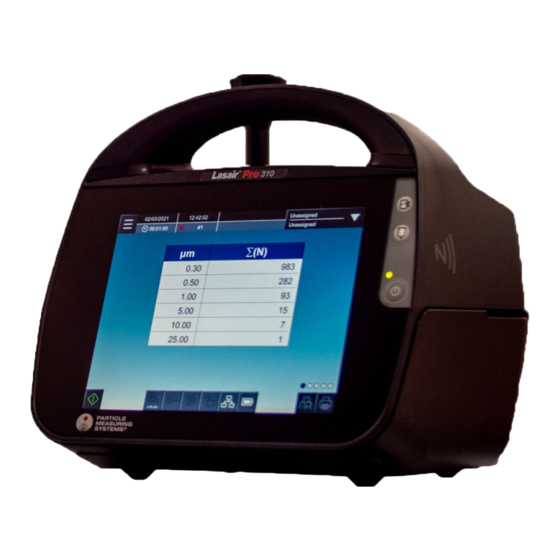
Chapter 1 Quick Guide Portable, lightweight, and durable, the Lasair® Pro Aerosol Particle Counter is especially useful in applications where portability is important, such as cleanroom monitoring, facility certification, and trending analysis. SAMPLE INLET MODEL HANDLE PAPER CUT PAPER FEED POWER TOUCHSCREEN Lasair®... - Page 21 Chapter 1 : Quick Guide The particle counter’s touchscreen controls and intuitive user interface make setup for particle sampling simple. You can easily: • Set the start and stop time intervals for particle sampling • Display sampling results • Set alarm parameters •...
-
Page 22: Assembly
Chapter 1 : Quick Guide Assembly Remove the protective cap from the particle counter’s sample inlet. Press tubing or ISP over the sample inlet base. If using tubing, insert the free end of the tubing into one end of an adapter (supplied with each ISP). -
Page 23: Home Screen
Chapter 1 : Quick Guide HOME Screen CURRENT DATE SUCCESS INDICATOR OPENS NAVIGATION CURRENT SAMPLE #/TOTAL # CURRENT TIME SAMPLE ROOM/LOCATION TIME/VOLUME RECIPE NAME SELECTION STATUS ICONS SECURITY BATTERY PRINT CURRENT SAMPLE START LASER SAMPLING DATA COMMUNICATION PUMP COINCIDENCE LOSS SAVE CURRENT SAMPLING DATA TO USB Figure 1-1. -
Page 24: Sampling
Chapter 1 : Quick Guide Sampling Press the POWER button. On the HOME screen, press The Lasair Pro takes a sample with default settings. To adjust these settings, > SETTINGS . The font for the current tab you are on navigate to >... -
Page 25: Saving A Recipe
Chapter 1 : Quick Guide Saving a Recipe After adjusting sampling settings, press Enter the Recipe Name using the keyboard. Press OK. You can view, select, and assign saved recipes by navigating to > Enabling Security > USERS . Press >... -
Page 26: Connections
Chapter 1 : Quick Guide Navigate to SETTINGS. Press Enable Security to move the dot from left to right. Select the administrator account. You will now be able to log in. Connections 4-20 MA IN 4-20 MA IN CH 3-4 CH 1-2 USB TYPE A AUX IN/OUT... -
Page 27: Using Nfc
Chapter 1 : Quick Guide Using NFC NFC cards can store one user’s credentials or one recipe configuration for ease of use. To enable NFC: Press , then (COMM). Go to the NFC tab and press the Enable Security, Enable Locations/Recipes, and Enable Write NFC indicators. - Page 28 Chapter 1 : Quick Guide Figure 1-4. Clone Export and Import buttons, SETUP tab, SYSTEM Press either of the following buttons: Choose Clone Export, press inside the File Name field to open the keyboard, or press to select Clone Export a file to overwrite.
- Page 29 Chapter 1 : Quick Guide This page is intentionally left blank. 1-10 Lasair® Pro Aerosol Particle Counter Operations Manual...
-
Page 30: Chapter 2. Specifications
Chapter 2 Specifications M OD E L 5100 Channels Up to 8 configurable Up to 8 configurable Up to 8 configurable channels from 0.3 to channels from 0.3 to channels from 0.5 to 25.0 µm 25.0 µm 25.0 µm Optional 2-channel pharmaceutical mode available. See CHANNELS Tab on page 12-14. - Page 31 Chapter 2 : Specifications M OD E L 5100 Remote • Real-time download to Facility Net, Pharmaceutical Net Pro, Operation FacilityPro SCADA NG, and FacilityPro SMART NG • USB download • Automatic clock adjustment with NPT server configuration Reports • Encrypted PDF exports •...
- Page 32 Chapter 2 : Specifications M OD E L 5100 Enclosure • Alcohol, 70% or 99.5% Cleaning • Hydrogen peroxide 6% Materials • Phenol or other phenolics • Quaternary ammonium salts • Hypochlorites/sodium hypochlorite 0.5% detergent • Peracetic acid and hydrogen peroxide combination Sample Tubing 3/8-inch 1/2-inch...
-
Page 33: Environmental Conditions
Chapter 2 : Specifications Environmental Conditions The following environmental conditions apply to the Lasair Pro particle counter: Operating Temperature Range 0 – 30 °C Humidity Range 5 – 95% RH non-condensing Storage and Transportation -20° – 50 °C Temperature Maximum Altitude 6,562 ft (2000 m) Installation Requirements •... -
Page 34: Chapter 3. Your System
Chapter 3 Your System How Lasair Pro Works The Lasair Pro takes in air at a set flowrate dependent on the model (28.3, 50, or 100 LPM) through the sample inlet to the sample chamber. In this chamber, a laser beam projects a beam against particles in the sample and causes light scatter. -
Page 35: Memory
Chapter 3 : Your System Memory The Lasair Pro particle counter has the memory capacity to store 10,000 complete data sets, which cannot be edited or altered (thereby meeting 21 CFR Part 11 compliance). Once this memory is full, the instrument automatically erases memory in order to add additional sampling data. -
Page 36: Touchscreen
Chapter 3 : Your System Touchscreen The particle counter has a large, 8.4-inch color touchscreen that makes it easy to see data, and includes an intuitive and easy-to-use navigation structure. Information can also be entered using a USB keyboard. The display can be easily configured to display information in 1 of 12 languages. -
Page 37: Home Screen
Chapter 3 : Your System HOME Screen When you first turn on the Lasair Pro particle counter, the HOME screen displays. You can also navigate to this screen any time by pressing and then (HOME). CURRENT DATE SUCCESS INDICATOR OPENS NAVIGATION CURRENT SAMPLE #/TOTAL # CURRENT... - Page 38 Chapter 3 : Your System Use the HOME screen for viewing sampling data in a variety of formats. All data formats can be viewed by swiping across the screen to the left or right. The screen position dots, circled in Figure 3-2, indicate which of the five total formats you are viewing. Figure 3-3.
-
Page 39: Environment Data Table
Chapter 3 : Your System Environment Data Table Use the Environment Data Table on the HOME screen to view data collected by any environmental sensors (such as a temperature and relative humidity sensor). The table contains four rows for each available analog channel and the following four columns: Name: Name set for the channel •... - Page 40 Chapter 3 : Your System Image Name Description Start Starts the sampling process. Stop Stops the sampling process. Available when Continuous Pump mode has been enabled. See ADVANCED Tab on page 5-6. • When the Start Pump button is first Start Pump pressed, it will start the pump.
- Page 41 Chapter 3 : Your System Image Name Description Terminates Monitoring Mode and Statistics Mode. • For more information on Monitoring Mode, Terminate see Monitoring Mode on page 5-8. • For more information on Statistics Mode, see Chapter 11. Lasair Pro Status Pump Indicates the status of the pump.
- Page 42 Chapter 3 : Your System Image Name Description Security Security Enabled, Administrator Security Enabled, Indicates the security of the Lasair Pro counter. Supervisor When pressed, a dialog box gives the following information: Security Enabled, • Status (Enabled, Disabled) Operator • User (Username or Not logged in) •...
- Page 43 Chapter 3 : Your System Image Name Description Battery Discharging/ Not Charging Indicates the status of the battery. When pressed, a dialog box gives the following information: Charging • Number of installed batteries • Charge level • Remaining time (in hours) Fully Charged •...
- Page 44 Chapter 3 : Your System Image Name Description When displayed, indicates that the sampling has exceeded alarm limits set for particle and environment values. Alarm The background of the HOME screen turns red and audio cues may start if configured. Alarms cease after acknowledgement.
-
Page 45: Shipkit List
Chapter 3 : Your System Shipkit List Review the list of items included with your shipment. If any items are missing, contact Particle Measuring Systems Customer Service Center at 1-877-475-3317 or email info@ pmeasuring.com. The list included with your shipment will be specific to your order and Lasair Pro model (310, 350 or 5100). - Page 46 Chapter 3 : Your System 5100 Lithium Ion Battery 1000025008 Quantity: 1 Quantity: 1 Quantity: 2 Power Supply Quantity: 1 P/N 1000024952 Power Cord Quantity: 1 P/N CMP-X (dependent on country) Lasair Pro Operations Manual Quantity: 1 P/N 1000012958 Table 3-2. Default shipkit list 3-13 Lasair®...
-
Page 47: Accessory List
Chapter 3 : Your System Accessory List The following is the list of accessories available for the Lasair Pro particle counter. Contact your local sales representative, call 1-877-475-3317, or email info@pmeasuring.com order. 5100 Tripod Adapter Quantity: 1 P/N 1000012955 P/N 1000012956 P/N 1000012957 Stainless Steel Isokinetic... - Page 48 Chapter 3 : Your System 5100 Zero-Count Front Filter Quantity: 1 Back P/N 90104050 P/N 90104052 P/N 90104055 Handheld ISP Quantity: 1 P/N 90101036 P/N 90101037 P/N 90101038 Temperature and Relative Humidity (TRH) Probe Quantity: 1 P/N 501050-01 Thermal Printer Paper Quantity: 2 P/N 1000024998 Table 3-3.
- Page 49 Chapter 3 : Your System 5100 Cleanroom Thermal Printer Paper Quantity: 2 P/N 1000024977 External Battery Charger Quantity: 1 P/N 90101118-10, One Bay, 115 V P/N 90101119-10, Four Bay, 115 V P/N 90101118-20, One Bay, 230 V P/N 90101119-20, Four Bay, 230 V Pelican Wheeled Transport Case...
- Page 50 Chapter 3 : Your System 5100 316L Stainless Steel Table Stand Quantity: 1 P/N 1000023413 NFC Card Quantity: Dependent on order P/N 1000025099 USB Storage Jump Drive and Cap Quantity: Jump Drive: 1 USB Cap: 1 Jump Drive USB Cap P/N 1000026003 P/N 1000013021 Table 3-3.
- Page 51 Chapter 3 : Your System 5100 Lasair Pro Validation Manual Quantity: 1 DataAnalyst Software Quantity: 1 P/N 450800 DataAnalyst Validation Manual Quantity: 1 P/N 90450800 Table 3-3. Accessory list 3-18 Lasair® Pro Aerosol Particle Counter Operations Manual...
-
Page 52: Storing Shipping/Packing Materials
Chapter 3 : Your System Storing Shipping/Packing Materials After unpacking the instrument, make sure to save and store all the shipping and packing materials for future use. These shipping containers and packing materials are made specifically to protect the Lasair Pro particle counter during initial shipments, as well as future calibration or return servicing shipments. - Page 53 Chapter 3 : Your System This page is intentionally left blank. 3-20 Lasair® Pro Aerosol Particle Counter Operations Manual...
-
Page 54: Chapter 4. Connections
Chapter 4 Connections This chapter describes the following types of connections: • Power on page 4-4 • Analog on page 4-6 Digital In/Out on page 4-14 • NFC Cards on page 4-15 • Computer Connections on page 4-16 • Back Panel Pinouts configurable by the user include AUX I/O, 4-20 mA IN, and 4-20 mA OUT. -
Page 55: Chapter 4. Connections
Chapter 4 : Connections 4-20 MA IN 4-20 MA IN CH 3-4 CH 1-2 USB TYPE A AUX IN/OUT 4-20 MA OUT POWER ETHERNET 19 VDC 7.89 A SERIAL EXHAUST BACK PANEL (1) Serial – The USB Micro B serial protocol allows you to transfer data and •... - Page 56 Chapter 4 : Connections Lay the Lasair Pro so that its screen is against a flat surface. Pin numbering and description are given below: AUX I/O Pin 1 Pin 2 Pin 3 Pin 4 Pin 5 Pin 6 Output Voltage +24 VDC +24 VDC +5 VDC...
-
Page 57: Power
Chapter 4 : Connections Power CAUTION Fluctuations in the AC Main supply voltage should not exceed +10% of the rated voltage range. The Lasair Pro is rated at 19 VDC (150 W) and can be operated with the AC to DC power adapter or internal batteries. -
Page 58: Ac Power
Chapter 4 : Connections AC Power Before connecting to an AC power source, ensure you have the following items: Item Comments External AC to DC power supply Standard U.S. Government Energy Information Administration (EIA) power input of 100-240 VDC, 50–60 Hz. Only use the included power supply to prevent damage and assure proper operation. -
Page 59: Analog
Chapter 4 : Connections Analog Included in this section: Environmental (Analog) Input on page 4-6 • Analog Output on page 4-11 • Environmental (Analog) Input You can connect up to four analog environmental sensors using the Lasair Pro particle counter’s 4-20 mA input connectors. These input connectors are located on the back panel of the Lasair Pro counter. - Page 60 Chapter 4 : Connections Figure 4-2. ENVIRONMENTAL tab, IN/OUT Each analog input can have a different value of the Scale and Offset values. These values are determined by the range of the sensors that are being used. A selection box to enable or disable the analog input. NAME Can be changed to name of the sensor such as Temperature or Humidity.
- Page 61 Chapter 4 : Connections Enable the #1 and #2 rows by pressing inside the appropriate # fields. When enabled, the vertical line beside the number will be blue in color: Figure 4-3. Enabling/disabling sensors Press inside the NAME field to define the sensor name. For example, “T” for temperature.
- Page 62 Chapter 4 : Connections Figure 4-4. Example environmental sensor table You can find the data display for your environmental sensors on the HOME screen by swiping left twice. When the sensor is operating, the current value and average value will update every second. See Figure 4-5. Lasair®...
- Page 63 Chapter 4 : Connections Figure 4-5. Environmental sensor data display, HOME screen NOTE: Analog data cannot be assigned to a location. It is advisable to include location details in the Name field if applicable. 4-10 Lasair® Pro Aerosol Particle Counter Operations Manual...
-
Page 64: Analog Output
Chapter 4 : Connections Analog Output The Lasair Pro counter can be enabled to generate a multichannel analog output for reading particle data on a separate device, such as a Programmable Logic Controller (PLC) or Proportional-Integral-Derivative (PID) controller. Analog outputs are generated using particle size channel limits. -
Page 65: Lasair Pro Analog 4-20 Ma Output Log Mode
Chapter 4 : Connections Min: Sets the minimum x-axis value of the log graphical display. • CHANNEL: Press the dropdown arrow to select the particle size to be used for • analog output generation. Channel units are set in the CHANNELS tab of the SYSTEM screen. - Page 66 Chapter 4 : Connections Equation 1: Particle counts to mA conversion Equation 2: mA to particle counts conversion 4-13 Lasair® Pro Aerosol Particle Counter Operations Manual...
-
Page 67: Digital In/Out
Chapter 4 : Connections Digital In/Out The Lasair Pro counter can be enabled for digital input and output for use with light tower and alarm devices. For digital output, alarms must be configured first (see Chapter 7). Figure 4-7. DIGITAL IN/OUT tab, IN/OUT Digital output can be configured in the following way: Enable for particle alarms: Enables digital output signals to be sent for every •... -
Page 68: Nfc Cards
Chapter 4 : Connections NFC Cards Near Field Communication (NFC) allows the Lasair Pro counter to read and write information stored on a portable card. The card can contain: • User data to facilitate logging into the particle counter without entering the same information into the touchscreen. -
Page 69: Computer Connections
Chapter 4 : Connections Computer Connections You can optionally connect the particle counter to a computer using control software for long term memory storage, as well as data analysis. If connecting the Lasair Pro to a computer directly or indirectly, you will need one of the following: Crossover cable (P/N AE1938): Use when connecting directly to a computer •... -
Page 70: Third Party Control Software
Chapter 4 : Connections Use the Ethernet option if data will be downloaded directly over the network. Use the Secure File or XML options if data will be downloaded manually. The Address field directly pertains to the Type option chosen. It is either the IP Address when selecting the Ethernet option, or the file path of the XML or Secure File. -
Page 71: Ip Address
Chapter 4 : Connections Figure 4-9. NETWORK tab, COMM The NETWORK tab of the COMM screen allows for the following configurations: • IP Address • Multicast Address • Network Mask • Enable PMS TCP • Gateway Address IP Address The Internet Protocol (IP) address consists of two portions: •... - Page 72 Chapter 4 : Connections Although there are a great many numbers in the range of 0.0.0.0 to 255.255.255.255, in almost all circumstances instruments are placed on a segregated private network that uses a greatly reduced set of numbers. The valid ranges are shown in the following table. Address Class Start A (24 Bit Range)
-
Page 73: Mac Address
Chapter 4 : Connections For large systems, IT personnel will dictate a network mask value, and the value may be different from what is shown in the table. Make sure the network mask is set as specified by IT. All PCs, routers and instruments on a network must use exactly the same network mask, or communication problems will arise. -
Page 74: Saving Network Settings
Chapter 4 : Connections In Particle Measuring Systems instruments the MAC address is set during production. The value is permanently stored in non-volatile memory on the main processor circuit board. (The MAC address will change if the main circuit board is replaced.) The MAC address may be displayed via the HyperTerminal (i.e., USB Micro B service interface) by using the status command. -
Page 75: Instrument To Laptop Ethernet Setup
Chapter 4 : Connections Instrument to Laptop Ethernet Setup There are two ways to establish a direct Ethernet link between a laptop (or other PC) and a Particle Measuring Systems instrument. The first way is to modify the PC Ethernet settings to work with the existing instrument settings. - Page 76 Chapter 4 : Connections NOTE: If you don’t see “Ethernet” as a network option, choose “LAN” or “Local Area Connection”. NOTE: Do not select anything with the word “Wireless” or the word “Virtual”. You should see a window similar to the following: Figure 4-11.
- Page 77 Chapter 4 : Connections Figure 4-12. Adjusted internet protocol properties Click the OK button to close the window. Click OK again to exit LAN configuration. Attach a network cable between the PC and the instrument. In your internet browser, type the IP address of the Lasair Pro. If security is enabled, you will be prompted to enter credentials.
-
Page 78: Method 2: Modifying Network Settings With Serial Commands
Chapter 4 : Connections Method 2: Modifying Network Settings with Serial Commands This method takes advantage of a Microsoft Windows feature called Automatic Private IP Addressing or APIPA. APIPA allows a PC to automatically assign itself an IP address even when no DHCP server is present to provide an address to the PC. - Page 79 Chapter 4 : Connections This page is intentionally left blank. 4-26 Lasair® Pro Aerosol Particle Counter Operations Manual...
- Page 80 Chapter 5 Sampling Options Default settings for sampling can be changed and applied to the next sample run. This chapter describes the general configuration options, with the following chapters contributing to operation, data display and collection: Security on page 6-1 •...
-
Page 81: Chapter 5. Sampling Options
Chapter 5 : Sampling Options SETTINGS Tab (SAMPLE). You should now see the SETTINGS tab. Press and then Figure 5-1. Sampling configuration settings Sampling Setup The user can configure a set number of samples or enable continuous sampling (∞). Number of samples: The Lasair Pro will perform the number of samples indicated •... -
Page 82: Delays
Chapter 5 : Sampling Options Delays Time in the format of HH:MM:SS can be added at the start or between samples. Purge: Initial delay before the start of sampling. • Intersample: Delay between samples if Number of samples is greater than one. •... -
Page 83: Buttons
Chapter 5 : Sampling Options Buttons Image Name Description Opens the keyboard to name the recipe configuration. For more Save as Recipe information on recipes, see Chapter Saves the Sampling Setup Report as a PDF to the USB key. This button is only activated when a USB key is inserted. -
Page 84: Example Sampling Setup Report
Chapter 5 : Sampling Options Example Sampling Setup Report Figure 5-2. Example Sampling Setup Report (page 1) The Sampling Setup Report summarizes the current user configuration of the following: SETTINGS and ADVANCED tab of the SAMPLE screen • GENERAL, PARTICLES, ENVIRONMENTAL, and TREND tab of the ALARMS screen •... -
Page 85: Advanced Tab
Chapter 5 : Sampling Options ADVANCED Tab Press ADVANCED at the top of the screen to access this tab. Figure 5-3. Advanced sampling settings Sampling Start The following choices determine how sampling will start on the Lasair Pro counter: Standard: Sampling start is determined with the HOME screen. •... -
Page 86: Options
Chapter 5 : Sampling Options Options The following options can be enabled or disabled: Cycle: Enables the continuous collection of a finite number of samples without the • user needing to press the Start button on the HOME screen after each sampling. The number of samples is set on the SETTINGS tab (Number of samples). -
Page 87: Monitoring Mode
Chapter 5 : Sampling Options Alarm Title Alarm Reason Figure 5-5. Final Sample Report example Monitoring Mode Monitoring mode uses preconfigured sampling plans for locations. When enabled, changes to sampling plans and their associated locations are restricted until the monitoring plan has been completed or cancelled. This mode works best when sampling plans are saved as recipes and assigned to locations. -
Page 88: Monitoring Mode Activation
Chapter 5 : Sampling Options Monitoring Mode Activation To activate Monitoring Mode: Deselect continuous sampling on the SETTINGS tab of the SAMPLE screen. On the ADVANCED tab of the SAMPLE screen, press inside the Number of sampling locations field and increase the number to 2 or greater. NOTE: The user can use previously created locations or virtual locations for their monitoring plan. - Page 89 Chapter 5 : Sampling Options You may also enable the Add virtual slider, which creates temporary locations to be used only for the sampling to be performed after enabling Monitoring Mode. These locations are labeled with the "Virtual loc #XXX" format, and are not stored by the system for later use.
- Page 90 Chapter 5 : Sampling Options Figure 5-8. Maximum and average counts You can also view average values for each location by swiping from left to right once more across the screen. Figure 5-9. Average counts for each location 5-11 Lasair® Pro Aerosol Particle Counter Operations Manual...
- Page 91 Chapter 5 : Sampling Options After each sample has completed, you will see the following message. Press OK to confirm. Figure 5-10. Sampling is complete at the selected location After samples have been collected at all locations you will see the following message.
-
Page 92: Example Cleanroom Monitoring Report
Chapter 5 : Sampling Options Figure 5-12. Confirmation window to terminate Monitoring Mode Example Cleanroom Monitoring Report Figure 5-13. Cleanroom Monitoring Report example Figure 5-14. 5-13 Lasair® Pro Aerosol Particle Counter Operations Manual... -
Page 93: Sampling Accessories
Chapter 5 : Sampling Options Sampling Accessories Sample Probes A standard isokinetic sampling probe (ISP), constructed out of Ultem® 1000, is included with the particle counter that can be mounted directly onto the instrument’s sample inlet. Or, to extend the reach of the sample probe, sample tubing can be added. Optional Probes The following isokinetic sampling probes (ISPs) are available and are dependent on the unit’s configuration. -
Page 94: Wall/Hand/Tripod Adapters
Chapter 5 : Sampling Options Wall/Hand/Tripod Adapters A wall/hand/tripod adapter, specific to the particle counter model, is included and shipped with each Lasair Pro particle counter. Additional adapters are available for purchase, if needed: • Wall/hand/tripod adapter (1 CFM) – P/N 1000012955 •... -
Page 95: Tubing
Chapter 5 : Sampling Options • 100 LPM Depending on the flowrate of the Lasair Pro Particle Counter, the size and the shape of the HHIPA horn are slightly different as well as the size of the barb fitting and tubing ID. Tubing All units are supplied with the same ergonomic handle, a barb fitting to attach tubing and 10 feet of tubing to connect to the Lasair Pro Particle Counter. - Page 96 Chapter 5 : Sampling Options Ordering the optional 100 dB Alarm Siren for the Lasair Pro Particle Counter provides the loudest and easiest-to-hear sound during this type of use. It is highly recommended to order the Lasair Pro with this additional feature if you are going to be using the HHIPA accessory.
- Page 97 Chapter 5 : Sampling Options This page is intentionally left blank. 5-18 Lasair® Pro Aerosol Particle Counter Operations Manual...
-
Page 98: Chapter 6. Security
Chapter 6 Security The Lasair Pro particle counter is shipped without security enabled, allowing first-time users to access all screens and settings. Access can be made limited by creating users and enabling security. Once enabled, there are four tiers of accessibility: administrator, supervisor, operator, and no login. -
Page 99: Security Overview
Chapter 6 : Security Security Overview See the following sections for information on individual SECURITY tabs: Settings Tab on page 6-10 • Users Tab on page 6-12 • Audit Tab on page 6-15 • Audit Data Tab on page 6-16 •... -
Page 100: Activate/Deactivate Users
Chapter 6 : Security NOTE: Permissions are the same for NFC access levels. For example, Administrator and Administrator NFC have the same permissions. A summary of the accessible instrument screen/menu for each access level is provided in Table 6-2. Screen No Login Operator Supervisor... - Page 101 Chapter 6 : Security NOTE: When security is enabled, the Lasair Pro prevents the disable of the Administrator account currently logged into the instrument. NOTE: When security is enabled, the Lasair Pro prevents an administrator from disabling their own account. In order to disable the current administrative account, security must be disabled or another administrative user must log in to the instrument.
- Page 102 Chapter 6 : Security You should now see the new user listed beneath the column headers. Select the portion of the row under the ON/OFF column to activate the user. The vertical line beside the row number will be orange when activated. Figure 6-3.
- Page 103 Chapter 6 : Security Disabling Security Security can only be disabled by an administrator. Log in to an administrator account. Press , then (SECURITY). Go to the SETTINGS tab and press the Enable Security slider. The orange indicator will fade in color and move to the left side before the HOME screen automatically appears.
- Page 104 Chapter 6 : Security Figure 6-4. NFC tab, COMM Press and then (SECURITY). Go to the USERS tab and press Select any type of NFC user (Operator NFC, Supervisor NFC, or Administrator NFC) from the Access level dropdown. Your username will generate automatically. Press inside the Password and Confirm password fields to open the keyboard and enter your password.
- Page 105 Chapter 6 : Security Select the recently created NFC user from the User dropdown. Press inside the NFC operator name field and enter your personalized username. Press Write. Press your NFC card to the NFC card reader located on the right side of the Lasair Pro counter.
- Page 106 Chapter 6 : Security Figure 6-6. Orange circular waiting animation Once complete, the message NFC USER card is successfully written will appear in green. The NFC user can now use this specific card to log into the Lasair Pro counter without using the keyboard. NOTE: If user information has already been written to the NFC card, the older data will be automatically overwritten.
-
Page 107: Settings Tab
Chapter 6 : Security Settings Tab Figure 6-7. SETTINGS tab, SECURITY The SETTINGS tab allows an administrator to enable or disable security, enable or disable the auto-logout feature,and configure password settings. All settings are described in Table 6-3 on page 6-11. 6-10 Lasair®... - Page 108 Chapter 6 : Security Image Name Description GENERAL Enables all security features. Security cannot be enabled if Enable Security there is no administrator account has been enabled. Enables the Lasair Pro counter to automatically log the user out Auto Logout at the end of a specified time period.
-
Page 109: Users Tab
Chapter 6 : Security Users Tab Figure 6-8. List of users The primary feature of this tab is a table with all entered users. A lock icon appears next to the logged-in administrator inside the Access Level column. The table has the following columns: ON/OFF: Allows the administrator to enable or disable specific users of the Lasair •... - Page 110 Chapter 6 : Security Image Name Description Allows for the entry of a new user. The Administrator user can add up to 100 users to be saved on the Lasair Pro. The user name, password, and access level can be Modify modified after user creation.
-
Page 111: Example User Setup Report
Chapter 6 : Security Example User Setup Report Figure 6-9. Example User Setup Report To generate your User Setup Report: The report will list all current users. If no users are created, the report will generate an empty table. Press and then (SECURITY). -
Page 112: Audit Tab
Chapter 6 : Security Audit Tab Figure 6-10. Audit trail settings The Lasair Pro will gather all user activity into an audit trail, organizing by type and date/ time. To enable the audit trail functionality, toggle the Enable audit trail button so that the orange indicator dot is on the right. -
Page 113: Audit Data Tab
Chapter 6 : Security Audit Data Tab Figure 6-11. Audit Data listing The Audit Data tab lists the activities of configured users, grouped by the location of activity (Security, Recipe, Sampling, Data, etc). Default sorting is by date/time, with earliest shown first. Image Name Description... -
Page 114: Example Audit Report
Chapter 6 : Security Image Name Description When a USB key is inserted, pressing this button exports USB Export the current Audit Trail list to the inserted USB. The file type is PDF. Table 6-6. AUDIT DATA tab, SECURITY Example Audit Report Figure 6-12. - Page 115 Chapter 6 : Security NOTE: The CSV and XML exports generated on the AUDIT and AUDIT DATA tabs are identical. 6-18 Lasair® Pro Aerosol Particle Counter Operations Manual...
- Page 116 Chapter 7 Alarms Alarm limits can be set for all available particle and environmental channels. One particle alarm may be set for each particle size channel—and each particle alarm may be individually enabled or disabled. Use the following tabs to configure alarm settings: •...
-
Page 117: Chapter 7. Alarms
Chapter 7 : Alarms GENERAL Tab Figure 7-1. GENERAL tab, ALARMS The GENERAL tab allows the user to enable or disable the following options: • Enable Alarms: Enables all alarms (particle, environmental, and trend). When the button is disabled, all alarms and alarm settings are disabled. Alarms are triggered after warning limits are reached. -
Page 118: Particles Tab
Chapter 7 : Alarms PARTICLES Tab Figure 7-2. PARTICLES tab, ALARMS Use the PARTICLES tab to adjust the following: • Enable/disable the particle alarm for each channel • Set the particle warning and alarm limit for each channel. Warnings will trigger prior to alarms. -
Page 119: Triggering Value Column (Warning, Units)
Chapter 7 : Alarms Triggering Value Column (WARNING, Units) The second column of each half is the triggering value column. The triggering value column displays the triggering value of the channel. This is also the value at which the channel will activate a particle alarm for the sample. The unit of measure for the triggering value depends on the configuration of the SETTINGS tab of the SAMPLE screen. -
Page 120: Environmental Tab
Chapter 7 : Alarms ENVIRONMENTAL Tab Environmental (or analog) channel alarms are configured on the ENVIRONMENTAL tab of the IN/OUT screen (see Environmental (Analog) Input on page 4-6). The same analog channels displayed in the ENVIRONMENTAL tab of the ALARMS screen are also displayed on the HOME screen by swiping left. -
Page 121: Trend Tab
Chapter 7 : Alarms TREND Tab The TREND tab allows the user to define particle alarms for a trend graph. The triggering value of the alarm is displayed on the trend graph (see GRAPH Tab on page 10-16), and alarms can be set for each channel. When the alarm for a channel is set, it will display as a horizontal line on the graph with the color of the channel it belongs to. - Page 122 Chapter 7 : Alarms The TREND tab displays the trend alarms for all configured particle channels in tabular format. Going by column, the user is able to: µm: Enable or disable any trend alarm. • VALUE: Change the triggering value of the trend alarm. The units displayed here, •...
-
Page 123: Reasons Tab
Chapter 7 : Alarms REASONS Tab Figure 7-5. REASONS tab, ALARMS The REASONS tab allows the user to define pre-set alarm reasons to select for alarm acknowledgement of particle or environmental alarms. Alarm reasons can be created, deleted, modified, enabled, and disabled. All alarm reasons are automatically enabled after creation. - Page 124 Chapter 7 : Alarms Delete Deletes the selected alarm reason from the Lasair Selected Pro. A confirmation window appears before the Alarm reason is deleted. Alarms that have been used to an Reason acknowledge an alarm will not be deletable. Delete Deletes all alarm reasons from the list.
-
Page 125: Assigning Alarm Reasons
Chapter 7 : Alarms Assigning Alarm Reasons If a sample contains a particle or analog warning or alarm and the Enable Alarms Reasons option is active (see GENERAL Tab on page 7-2), the Alarm Acknowledgement button appears on the HOME screen. If a warning limit has been reached, the font color for the channel(s) affected will change from black to yellow. - Page 126 Chapter 7 : Alarms Figure 7-7. Particle Alarm information Figure 7-8. Particle Warning information The Alarm Acknowledgement window allows the user to view alarm details and either define an alarm reason to apply to the sampling data, or select an alarm reason defined in the REASONS Tab to apply to the sampling data.
- Page 127 Chapter 7 : Alarms NOTE: When acknowledging alarms, the option Apply to all remaining samples only applies that alarm acknowledgement to samples that have already been taken. It does not apply to any samples in progress, or that have not been started.
-
Page 128: Chapter 8. Locations
Chapter 8 Locations If you are moving the instrument to different sampling points, the Lasair Pro particle counter lets you categorize and name these points in LOCATIONS. Figure 8-1. Locations configuration for recipes Areas, rooms, and locations can be added individually or generated automatically with numbering between 1 and 100. - Page 129 Chapter 8 : Locations Figure 8-2. Hierarchy of areas, rooms, and locations You are free to add only the items you need. For example, you may choose to only use locations to refer to your critical sampling points, forgoing the use of rooms and areas. Areas, rooms, and locations are selectable from the HOME screen once created, and sampling data will be labeled with location data whether it is assigned or unassigned.
- Page 130 Chapter 8 : Locations Adding a New Area, Room, and Location If you plan to use the Lasair Pro for multiple sampling points, you can add these locations and organize them ahead of time to ensure sampling data is appropriately labeled. >...
- Page 131 Chapter 8 : Locations again, and select Room as the Item type. Press From the Parent item dropdown, select your previously created Area to assign the area to the room. Press OK to confirm your selection. again, and select Location as the Item type. Press From the Parent item dropdown, select your previously created Room to assign the location to the room.
- Page 132 Chapter 8 : Locations In the Auto Fill dialog, press inside the fields to configure the entry with the keyboard: The Base name is the text applied to each entry. The Number determines how many entries will be generated. Press OK. Choose the next largest option from the Type dropdown.
- Page 133 Chapter 8 : Locations Figure 8-5. Type listing circled You can also print a summary with either the buttons. NOTE: Selecting an Area and/or Room with the dropdown arrows automatically populates those fields after using the button. NOTE: When using the button for adding multiple locations and/or rooms within a hierarchy, select the Parent items (Area and/or Room) using the dropdown arrows for automatic assignment.
- Page 134 Chapter 8 : Locations Assigning a Location to a New Sample On the HOME screen, select , displays the Area and Room listing. The bottom button, The top button, , displays the Room and Location listing. Figure 8-6. Area and Room assignment list Double tap the Room or Location selection to complete.
- Page 135 Chapter 8 : Locations Press to delete all location and assignment data. Recipes will become unassigned by default after this action. Figure 8-7. Delete all location facility data After confirming deletion by pressing OK, you will have the option to recover data until the Lasair Pro instrument is restarted.
-
Page 136: Buttons
Chapter 8 : Locations Buttons The following table lists the buttons of the LOCATIONS screen. Image Name Description Edit Item Allows the modification of the selected entry. Enables the entry of a new area, room, or Add Item location. Remove Removes selected area, room or location data. -
Page 137: Example Location Hierarchy Report
Chapter 8 : Locations Example Location Hierarchy Report Figure 8-9. Example Location Hierarchy Report The Location Hierarchy Report displays areas, rooms, locations and their assignments configured in the LOCATIONS tab of the LOCATIONS screen. 8-10 Lasair® Pro Aerosol Particle Counter Operations Manual... -
Page 138: Chapter 9. Recipes
Chapter 9 Recipes A recipe is a set of sampling or statistical parameters which can be saved and recalled by name or by location. Recipes not only save time and effort, but add a quality control measure to ensure consistency between locations and among employees. Up to 100 recipes can be stored on the Lasair Pro. -
Page 139: Chapter 11. Statistics
Chapter 9 : Recipes Creating a New Recipe Recipes save the current configurations found in SAMPLE, ALARMS, LOCATIONS, and STATISTICS. > After configuring sampling settings, navigate to (SAMPLE). Press to open the keyboard to name the new recipe. Recipe names can include up to 16 characters. - Page 140 Chapter 9 : Recipes Figure 9-2. RECIPES DETAILS window Press to save the recipe to a USB. Press to print the recipe using the thermal printer. Press OK when finished. Lasair® Pro Aerosol Particle Counter Operations Manual...
- Page 141 Chapter 9 : Recipes Assigning a Location to a Recipe Recipe use can be limited to a specific location, area, or room. (RECIPES), select the ASSIGNMENTS tab. From Press and choose the recipe, area and room from the dropdown menus. Select the Location from the adjacent list.
- Page 142 Chapter 9 : Recipes Creating NFC Recipes Recipes can be stored to an NFC card so the user can easily switch between recipes configured for different areas, rooms, and locations. A maximum of 50 locations can be used with one NFC recipe card. Press , then (COMM).
- Page 143 Chapter 9 : Recipes Press and then (RECIPES). On the ASSIGNMENTS tab, you should see a list of your created recipes and their area, room, and location assignments. If you have not assigned the recipe to an area, room, and location, do so now. See Assigning a Location to a Recipe on page 9-4 for more information.
-
Page 144: Setup Tab Buttons
Chapter 9 : Recipes Once complete, the message NFC RECIPE card is successfully written will appear in green. The NFC user can now use this specific card to sync the recipe configuration with the Lasair Pro counter without using the keyboard. NOTE: If user information has already been written to the NFC card, the older data will be automatically overwritten. - Page 145 Chapter 9 : Recipes Image Name Description Saves the highlighted recipe to the attached USB key. There are three types of recipe reports: Certification, Monitoring, and Sampling. The button is enabled only when the USB is attached. Certification: This report lists the current settings found on •...
-
Page 146: Assignments Tab Buttons
Chapter 9 : Recipes ASSIGNMENTS Tab Buttons Use the ASSIGNMENTS tab to associate a recipe to an area, room, location, or all three. Image Name Description Opens a configuration window to assign a specific recipe to any combination of area, room, and Assignment location. -
Page 147: Recipe Importing And Exporting
Chapter 9 : Recipes Recipe Importing and Exporting Lasair Pro recipes can be imported and exported to other Lasair Pro counters. See Clone Export and Import on page 12-8. Be aware of the following: • Moving a recipe between instruments with different flowrates may result in unexpected sample times or sample volumes. - Page 148 Chapter 9 : Recipes • Sample units (ft³, m³, or l) • Data display (Raw or Normalized) • Auto print sample (On/Off) • Auto print sample average (for two or more samples) • Auto print to USB-key (On/Off) • Beep mode (On/Off) •...
-
Page 149: Statistics Recipe Details
Chapter 9 : Recipes Statistics Recipe Details Statistics recipes are found in the same list as normal recipes. Statistics recipes are saved on the SETUP tab of the STATISTICS screen. See SETUP Tab on page 11-9. The following is the list of all parameters saved for a statistics recipe: •... - Page 150 Chapter 10 Display, Data and Reports The tabs of the DISPLAY screen allow the user to adjust screen and sound parameters, configure channel settings, set graphical displays, and insert report data. Tabs under the DATA screen allow the user to view previous sampling data in a variety of formats. You can view sample data in a number of ways on the HOME and DATA screens, in addition to reports.
-
Page 151: Chapter 10. Display, Data And Reports
Chapter 10 : Display, Data and Reports DISPLAY Tab Figure 10-1. DISPLAY tab, DISPLAY Use the Options tab to adjust the display brightness, screen saver, alarm signal volume, and click button volume. Table 10-1 describes all settings on this tab. Image Name Description... - Page 152 Chapter 10 : Display, Data and Reports Image Name Description Enables the screen saver feature. Press the Time (min) field to access the keyboard for entering the number of minutes (1 - 60) of inactivity required before the screen saver is activated. Screen Saver •...
-
Page 153: Trend Tab
Chapter 10 : Display, Data and Reports TREND Tab Figure 10-2. TREND tab, DISPLAY The options of the TREND tab of the DISPLAY screen pertain to the fourth display option ) on the MAIN screen. See Table 10-2 for a description of each option. Image Name Description... - Page 154 Chapter 10 : Display, Data and Reports Image Name Description SETTING The interval (total time span) to Minutes display on the trend graph’s x-axis. Displays the moving average value as a dashed line on the graph for Moving averages two channels. The moving average value is the mean value for the N last samples, where N is the Size option.
-
Page 155: Example Trend Graph
Chapter 10 : Display, Data and Reports Image Name Description This option allows all sampling data to be displayed on the graph. The Auto scale maximum value for the y-axis scale adjusts automatically. The minimum value to display for the y-axis. -
Page 156: Histogram Tab
Chapter 10 : Display, Data and Reports HISTOGRAM Tab Figure 10-4. HISTOGRAM tab, DISPLAY On the Histogram tab, you can configure settings for the graphical and report data display. See Table 10-3 on page 10-7 for a description of each setting on this screen. Image Name Description... - Page 157 Chapter 10 : Display, Data and Reports Image Name Description Sets differential as the type of data to be used for the histogram graph. Differential Data Differential Count refers to a number of particles of certain size that are found in one sample. DISPLAY MODE Sets the histogram to show the percentages for all enabled channels.
-
Page 158: Reports Tab
Chapter 10 : Display, Data and Reports REPORTS Tab Figure 10-5. REPORTS tab, DISPLAY Reports can be personalized to include additional text used in the report layout for PDF files. The REPORTS tab allows the user to add the following text to sampling reports: •... -
Page 159: Reports Overview
Chapter 10 : Display, Data and Reports Reports Overview You can output sampling results to the following: • Built-in thermal printer • USB key • PMS software such as DataAnalyst, FacilityPro and Pharmaceutical Net Pro NOTE: For information about transferring sampling data to PMS software, see the user guide that comes with the software. -
Page 160: Final Sample Report Example
Chapter 10 : Display, Data and Reports Final Sample Report Example 21 CFR Part 11 Compliant Final Sample Report 2 Heading 1 3 Heading 2 4 Instrument ID: Lasair Pro 5 Serial Number: 82217 6 Calibrated: 01/01/2020 7 Batch ID: 00021 8 Operator: John Doe... - Page 161 Chapter 10 : Display, Data and Reports Line No. Displayed Text Description Title of Report. Possible values: Final: Report printed after the sampling • Final Sample completed. Report Partial: Report printed during the sampling • process. Heading 1 text specified in the REPORTS tab of the Heading 1 DISPLAY screen.
- Page 162 Chapter 10 : Display, Data and Reports Line No. Displayed Text Description Started: Date stamp (day / month / year) followed by a time 04/01/2020 stamp (hour : minute : second) when the sample was 13:57:07 started. Date stamp (day / month / year) followed by a time stamp (hour : minute : second) when the sample ended.
- Page 163 Chapter 10 : Display, Data and Reports Line No. Displayed Text Description Volume: Total volume of medium (e.g., air) sampled. Volume Flow: Flowrate of the medium during sampling. Flow For thermal printouts of sampling reports, this information is below Environmental Data. Total sampling time.
-
Page 164: Data Screen
Chapter 10 : Display, Data and Reports DATA Screen Results of individual samples and trending of multiple samples can be viewed with the tabs of the DATA screen. TABLE Tab Figure 10-6. Table display of sampling data The TABLE tab of the DATA screen displays all sampling and environmental sensor data stored internally on the Lasair Pro counter in a list format. -
Page 165: Graph Tab
Chapter 10 : Display, Data and Reports All of the following columns can be filtered: • DATE/TIME • Configured Particle Channel Readings • LOCATION • Configured Analog • OPERATOR Readings • SAMPLE TIME • ALARM REASON • VOLUME GRAPH Tab Figure 10-7. - Page 166 Chapter 10 : Display, Data and Reports The GRAPH tab is for viewing four possible graphical displays: • A. Historical Trend ( ): Particle counts over time for all configured channel sizes. Multi-colored lines represent individual channels. Used for trending data over multiple samples.
- Page 167 Chapter 10 : Display, Data and Reports Each graphical display can be generated as a report. Press on each graphical display to send the report to an inserted USB key. See Figure 10-9 for examples. Figure 10-9. Graphical report examples 10-18 Lasair®...
- Page 168 Chapter 10 : Display, Data and Reports Buttons Image Name Description Automatically adjusts scaling to show all data Auto Scaling values. Press and hold to display information for each channel’s graph. There are two legends, one for each channel. Each legend has the following information: Solid box: Line color and style for •...
- Page 169 Chapter 10 : Display, Data and Reports Image Name Description Opens general display options, which include the following: • Cumulative or differential counts • Raw or normalized counts Options • Units of volume • Linear, log, or % of full scaling •...
-
Page 170: Options
Chapter 10 : Display, Data and Reports Options Figure 10-10. Options dialog Data Allows the user to configure the units of their sampling data. • Cumulative(∑): Sets the data display to cumulative counts only. • Differential(Δ): Sets the data display to differential counts only. •... - Page 171 Chapter 10 : Display, Data and Reports Channels Allows the user to: • Configure which configured size channels will be included in the display. Channels can be configured in the CHANNELS tab of the SYSTEM screen. Enable Moving averages, which is the sampling average displayed beside the •...
-
Page 172: Chapter 11. Statistics
Chapter 11 Statistics Overview The Lasair Pro particle counter can be configured for certification statistics when in Statistics Mode. A choice of certification standards includes ISO 14644-1:2015, FS-209E, EU GMP, and AVERAGE. Selecting the certification standard and class automatically sets the particle count limits for the sampling location. -
Page 173: Home Screen
Chapter 11 : Statistics HOME Screen In Statistics Mode, the HOME screen and its data displays are adjusted to include the standard, limits, and locations configured on the STATISTICS screen. Refer to Figure 3-2 on page 3-4 for the details not described in Figure 11-2. REMAINING VOLUME COMPLETED LOCATIONS/TOTAL TO BE SAMPLED... -
Page 174: Data Displays
Chapter 11 : Statistics Data Displays Figure 11-3. Swipe left to switch between displays In Statistics Mode, the following data displays are available on the HOME screen: • A. Cumulative particle count display: For each channel size, the table displays the particle count limit to meet the standard, and the cumulative particle count for the current volume sampled at the location. -
Page 175: Average Mode
Chapter 11 : Statistics NOTE: All particle count data is normalized, meaning it has been divided by the sample volume. NOTE: When the Statistics Mode is enabled, TCP/IP communications are disabled. NOTE: When Statistics Mode is enabled, global alarms are automatically disabled. You must exit Statistics Mode to change alarm parameters. -
Page 176: Results
Chapter 11 : Statistics Figure 11-4 shows the following adjustments to the HOME screen: • A. Average and cumulative normalized counts: Average values refer to the mean particle count data for all samples across all locations, directly comparable to cumulative normalized counts (counts of a certain particle size and larger over the configured sample volume) for all locations. - Page 177 Chapter 11 : Statistics Figure 11-5. Average mode report, first page Data unique to this report include the following: • Average particle count of a certain size for all samples (Mean), maximum particle count of all samples for a certain particle size (Max), how different each sample differs from the mean of all samples or standard deviation (SD), and 95% upper confidence limit (95% UCL) for each particle size.
-
Page 178: Switch Mode
Chapter 11 : Statistics Switch Mode After enabling Statistics Mode, the user is prompted for a selection of locations. Previously created areas, rooms, and locations can be selected here, in addition to virtual locations. Virtual locations are not stored for later use in the Lasair Pro, but are generated specifically for one-time use after Statistics Mode is enabled. -
Page 179: Standards Tab
Chapter 11 : Statistics STANDARDS Tab Figure 11-7. STANDARDS tab, STATISTICS The following configurations can be made on the STANDARDS tab: Standard: Set the cleanliness standard to determine the particle count limits for • an area. Class: Set the cleanliness level of the area to be certified. •... -
Page 180: Setup Tab
Chapter 11 : Statistics SETUP Tab Figure 11-8. SETUP tab, STATISTICS Configuration Settings The following table describes the settings the users can configure before enabling Statistics Mode. Once Statistics Mode is enabled, settings cannot be changed until the Statistics plan has been terminated. Image Name Description... - Page 181 Chapter 11 : Statistics Image Name Description Sets the Area units in squared feet. Units cannot be changed once Statistics Mode is enabled. SETTINGS Sets the minimum number of the locations to be sampled. The number is automatically Number of calculated to comply with the Locations selected standard based on the...
- Page 182 Chapter 11 : Statistics Image Name Description ENABLE / DISABLE OPTIONS Enables Statistics Mode. When enabled, the user is prompted to select the area, room, and location for certification. After pressing OK, the HOME screen Enable automatically appears with Statistics statistics sampling criteria Mode loaded.
-
Page 183: Example Certification Setup Report
Chapter 11 : Statistics Example Certification Setup Report Figure 11-9. Certification Setup Report example The Certification Setup Report displays the current parameters of the STANDARDS and SETUP tabs of the STATISTICS screen. 11-12 Lasair® Pro Aerosol Particle Counter Operations Manual... -
Page 184: Walkthrough
Chapter 11 : Statistics Walkthrough This section describes the general step-by-step process of conducting a statistics plan. The following is an example only. Press and then (STATISTICS). Configure the STANDARDS and SETUP tabs. In this example, we will be using the ISO 14644-1:2015 standard for ISO Class 7. - Page 185 Chapter 11 : Statistics Figure 11-10. Switch Mode window, virtual locations added Figure 11-11. Automatic list of virtual locations, HOME screen Press OK when done. You will be automatically taken to the HOME screen. When ready, press the button to begin sampling. 11-14 Lasair®...
- Page 186 Chapter 11 : Statistics After the sample has completed, you will see either of the following messages. If you did not enable Sample Confirmation, you will see Figure 11-12. If you enabled Sample Confirmation, you will see Figure 11-13. NOTE: If you choose to reject the sample data, it will not be used in the final report.
- Page 187 Chapter 11 : Statistics After sampling is complete, you will receive the following message. Figure 11-14. Statistics plan complete message To save and view the report data, you have the following options: • Swipe left across the touchscreen to view all the data displays. •...
-
Page 188: Statistics Report Example
Chapter 11 : Statistics Statistics Report Example The following is an example of the Lasair Pro particle counter’s Statistics Report generated when a room is certified to the ISO 14661-1 standard. The lines have been numbered to match the accompanying table containing their descriptions. 21 CFR Part 11 Compliant Cleanroom Certification Report 2 Heading 1... - Page 189 Chapter 11 : Statistics Particle Data µm 30 TARGET 0.30 10200.0 31 Max 0.30 32 Mean 0.30 33 SD 0.30 TARGET 0.50 3520.0 0.50 Mean 0.50 0.50 TARGET 1.00 832.0 1.00 Mean 1.00 1.00 TARGET 5.00 29.0 5.00 Mean 5.00 5.00 Location Averages Location...
- Page 190 Chapter 11 : Statistics Line No. Displayed Text Description Heading 2 text specified in the REPORTS tab of the Heading Two DISPLAY screen. Not shown if Heading One field is blank. Name/ID of the particle counter that produced the Instrument ID data.
- Page 191 Chapter 11 : Statistics Line No. Displayed Text Description The classification the room is being tested against. Standard Class The Standard Class determines the particle limits to meet classification. Particle Size & Refers to the column headers for particle sizes of Limits interest and their limits to meet classification.
- Page 192 Chapter 11 : Statistics Line No. Displayed Text Description The particle size of interest. For column definitions, TARGET see line 29 above. The maximum value of the samples averaged. Mean of all locations. For column definitions, see line Mean 29 above. Standard Deviation of all location means.
-
Page 193: Iso 14644-1:2015 Standard
Chapter 11 : Statistics Cleanliness Standards The standards tables in this section are reproductions of those found in their respective documents, and are supported by the Lasair Pro particle counter. The blank areas of the tables represent invalid settings. For example, the ISO 14644-1 standard does not allow certification of a Class 1 cleanroom using a 0.3 µm or greater particle size. -
Page 194: Eu Gmp Annex 1 Standard And China Gmp
Chapter 11 : Statistics EU GMP Annex 1 Standard and China GMP As a derivative of the ISO standard, the EU GMP Annex 1 standard uses most of the ISO rules. However, a comparison of maximum particle counts between the two standards shows that the EU GMP Annex 1 is slightly different. -
Page 195: Fs-209E Standard
Chapter 11 : Statistics FS-209E Standard ISO 14644-1 is used in place of the FS-209E standard globally, but the Lasair Pro particle counter still implements the classes specified in Table 11-6. Note that 0.1 and 0.2 µm particle sizes are not counted with the Lasair Pro. Maximum Particles Per Unit Volume Class 0.1 µm... -
Page 196: Chapter 12. System Configuration
Chapter 12 System Configuration Use SYSTEM to set general system options such as the instrument ID, calibration warning, language, date format, channel size, and sampling medium. You can also view the status of the instrument, including firmware version, the last calibration date, laser and pump information, and battery life. -
Page 197: Setup Tab
Chapter 12 : System Configuration Press to generate the Instrument Status Report, which summarizes the information of the STATUS tab of the SYSTEM screen. SETUP Tab Figure 12-2. SETUP tab, SYSTEM Instrument ID Press inside the field to open the keyboard to personalize the particle counter indentification. -
Page 198: Gas
Chapter 12 : System Configuration Allows the user to set the gas medium and its specific density in kg/m . Choices of gas include: • Air (1.205 kg/m • (1.842 kg/m • Argon (1.661 kg/m • Nitrogen (1.165 kg/m Language The Lasair Pro interface supports several international languages: •... - Page 199 Chapter 12 : System Configuration Figure 12-3. Change to another language keyboard NOTE: Some symbols are shown in the top-left of the numeric character buttons. Press and hold until the field is populated with the symbol. NOTE: Some keyboard letters only display when the user holds down their finger against a displayed letter for 2 - 3 seconds.
- Page 200 Chapter 12 : System Configuration Figure 12-4. Press and hold the ‘s’ letter on the DE keyboard for more options Other examples of additional letters not shown in the keyboards main display include the following: Press and hold..to generate this list of characters. ‘a’...
- Page 201 Chapter 12 : System Configuration Press and hold..to generate this list of characters. ‘e’ è, é, ê, ë, ē, ė, ę ‘u’ ù, ú, û, ū, ü ‘i’ ì, í, î, į, ī, ï ‘o’ ò, ó, ô, õ, ö, ø, œ, o ‘a’...
- Page 202 Chapter 12 : System Configuration Press and hold..to generate this list of characters. ‘e’ è, é, ê, ë, ē, ė, ę ‘o’ ò, ó, ô, õ, ö, ø, ō, œ ‘a’ à, á, â, ã, ä, å, æ, ā, ą ‘s’...
-
Page 203: Clone Export And Import
Chapter 12 : System Configuration Clone Export and Import The Lasair Pro system and data can be cloned and copied to another Lasair Pro instrument. Settings in the clone file include: All SYSTEM screen parameters • • Area, Room, Locations and assignments All SAMPLE screen parameters •... - Page 204 Chapter 12 : System Configuration Press either of the following buttons: Exports a file to the attached USB with selected Clone Export parameters. You may choose to encrypt the file. Imports previously exported files using the Clone Clone Import Export button. Choosing Clone Export opens the following window.
-
Page 205: Buttons
Chapter 12 : System Configuration Choosing Clone Import opens the following window. Figure 12-7. Clone Import window Press inside the File Name field to open the keyboard to type the name of the import file, or press to select a file to import. Select the options to be imported and press OK. - Page 206 Chapter 12 : System Configuration Image Name Description Clones the following settings into a Clone Export file that can be transferred to another Window Lasair Pro counter via USB key. Allows instrument to read and load a clone file from the USB key. After Clone Import pressing OK, the Lasair Pro will logout Window...
-
Page 207: Date/Time Tab
Chapter 12 : System Configuration DATE/TIME Tab Figure 12-8. DATE/TIME tab, SYSTEM The DATE/TIME tab allows the user to set the formats of both date and time, used on the HOME screen, sampling data, and reporting. Table 12-2 lists the options available for the user to configure. - Page 208 Chapter 12 : System Configuration Image Name Description Press the clock icon to set the current time for your time Time zone. The time displays in a format of hh:mm:ss for hours, minutes, and seconds. Enables or disables Network Time Protocol (NTP). Use if you are synchronizing the time Use NTP display of multiple Lasair Pro...
-
Page 209: Channels Tab
Chapter 12 : System Configuration CHANNELS Tab The CHANNELS tab allows the user to switch between All channels mode and Pharmaceuticals mode. All channels mode: Enables all eight particle size channels for use with sampling. • Pharmaceuticals mode: Enables only the 0.5 and 5.0 particle size channels. •... -
Page 210: Buttons
Chapter 12 : System Configuration NOTE: Changing between Pharmaceuticals mode and All channels mode is confirmed by pressing . This will cause the Lasair Pro to reboot and reconfigure itself. All existing data is deleted. Buttons Image Name Description Dropdown Press to open the dropdown menu for either the Available Mode or channel size. - Page 211 Chapter 12 : System Configuration This page is intentionally left blank. 12-16 Lasair® Pro Aerosol Particle Counter Operations Manual...
- Page 212 Chapter 13 Maintenance and Diagnostics This chapter describes the maintenance you can perform at your location, and includes information for: Cleaning and Disinfecting the Enclosure on page 13-1 • Replacing the Printer Paper Roll on page 13-3 • • Calibration Reminder on page 13-4 •...
-
Page 213: Chapter 13. Maintenance And Diagnostics
Chapter 13 : Maintenance and Diagnostics Recommended Cleaning Agents The following cleaning agents are recommended to clean and disinfect the enclosure case of the particle counter: • Bleach, typically 0.5 - 1% concentration • Ethyl/isopropyl alcohol (in a solution of less than 70%) •... -
Page 214: Replacing The Printer Paper Roll
Chapter 13 : Maintenance and Diagnostics Remove the sample probe and cover the sample inlet. Dampen a cleanroom wipe or other cloth with the cleaning solution and then wipe the enclosure case and screen. Follow this cleaning solution wipe, with a wipe or cloth damped with water. Replacing the Printer Paper Roll Pull the right case cover out with the finger notch. -
Page 215: Battery Disposal
Chapter 13 : Maintenance and Diagnostics Battery Disposal At end-of-life, batteries should be recycled or discarded safely. However, you need to follow your local guidelines for battery disposal. Your local waste authority will have information on return and collection systems in your area. Calibration Reminder Calibration should be performed once each year. -
Page 216: Diagnostics
Chapter 13 : Maintenance and Diagnostics Diagnostics The Lasair Pro performs automatic diagnostic tests daily. You can view the results of this test by navigating to the TESTS tab of the DIAGNOSTICS screen. Use the button in the bottom left to view PMS contact information. Figure 13-2. - Page 217 Chapter 13 : Maintenance and Diagnostics This page is intentionally left blank. 13-6 Lasair® Pro Aerosol Particle Counter Operations Manual...
-
Page 218: Appendix A. International Precautions
Appendix A International Precautions WARNING This instrument is designated as a Class 1 laser product and complies with US 21 CFR 1040.10 and EN 60825-1. Use of controls, or adjustment, or performance of procedures other than those specified in this manual may result in hazardous radiation exposure. AVERTISSEMENT Cet appareil est classé... -
Page 219: Hazard Symbols
Appendix A : International Precautions Hazard Symbols The meaning of hazard symbols appearing on the equipment is as follows: Symbol Nature of Hazard Attention, consult this document for warnings. Dangerous High Voltage Warning – Laser radiation! Avoid exposure to beam. Symboles de risque Des symboles représentant les risques sont placés sur l’appareil. -
Page 220: Warnschilder
Appendix A : International Precautions Warnschilder Die, an dem Gerat angebrachten Warnschilder haben folgende Bedeutungen: Symbol Gefahrenart Achtung, ziehen Sie dieses Dokument hinzu bei Warnhinweisen. Achtung Hochspannung Warnung – Laserstrahlung! Nicht in den Strahl blicken. Simboli di pericolo Il significato dei simboli di pericolo che appaiono sugli strumenti il seguente: Symbolo Natura del pericolo Attenzione, consultare questo documento per le avvertenze. -
Page 221: Simbolos De Peligro
Appendix A : International Precautions Simbolos de peligro Los simbolos de peligro que aparecen en el equipo significan: Símbolo Naturaleza del Peligro Atención, consulte este documento para ver las advertencias. Peligro alto voltaje. Advertencia – ¡Radiación láser! Evite exponerse al rayo. Lasair®... -
Page 222: Appendix B Serial Service Commands
Appendix B Serial Service Commands The Lasair Pro counter can be configured to communicate serially with a USB Micro B cable and terminal emulation software. Figure B-1. SERIAL tab, COMM NOTE: The serial interface mode is immediately activated upon selection and does not require the Lasair Pro to restart. - Page 223 Appendix B : Serial Service Commands Image Name Description Service mode reserved for use by PMS Service Service personnel. Baud Baud rate for serial I/O port. Data Bits are Rate locked at 8, with Stop Bits at 1. Table B-1. SERIAL tab, COMM Serial Service Commands Definitions of serial service commands are provided in the following sections: General Serial Service Commands on page B-3...
-
Page 224: General Serial Service Commands
Appendix B : Serial Service Commands General Serial Service Commands Command Description Run a DOS CHKDSK command to verify the chkdsk installed USB FLASH key is OK Sets the network addressing parameters to default factory defaults. Directory of installed USB FLASH key Display a table of battery status parameters get batt data for all four batteries... - Page 225 Appendix B : Serial Service Commands Command Description Set the buffer size for network protocol communications. This sets the number of samples which will be retransmitted by PMS TCP protocol in the event of a network outage. Default is 60 samples. Setting a large number may result in unexpected large amounts of network set buffer [buffer_size]...
- Page 226 Appendix B : Serial Service Commands Command Description Show the general network status of the instrument. Also show any Modbus TCP or PMS TCP clients that are attached to the instrument. Show a detailed listing of the instrument status. This command shows networking, sta full laser, blower, battery and sampling status parameters.
-
Page 227: User Selectable Channel Setup Commands
Appendix B : Serial Service Commands User Selectable Channel Setup Commands Command Description Display the list of current and new channel get channels settings. get channels table {[index]} Display the list of available particle sizes for each channel. An optional channel Range Limits index may be entered to limit the scope to a single channel. -
Page 228: Appendix C. Troubleshooting Ethernet
Appendix C Troubleshooting Ethernet Connectivity These steps may be used to check communications to an Ethernet device. Check for light on LEDs of the Ethernet connector. There should be at least one steady light to indicate a connection. If not, there is hardware connection problem. Is the cable bad? Try a different cable. - Page 229 Appendix C : Troubleshooting Ethernet Make sure the PC and the device are on the same network. Check the PC’s address by opening a command prompt and typing ipconfig. Is the Mask the same on both the PC and the device? Is the network portion of the address the same on both the PC and the device? Figure C-2.
-
Page 230: Appendix D. 有毒或有害的物质和元素
Appendix D 有毒或有害的物质和元素 有毒或有害的物质和元素 Part 铅 汞 镉 六价铬 多溴联苯 多溴联苯醚 Name (Pb) (Hg) (Cd) (Cr(VI)) (PBB) (PBDE) 部件名称 电源供应 印刷电路 装配 光学元件 激光 机械部件 电缆 机电 显示器 电池 O: 表示用于部件的所有同族物质中所含的有毒或有害物质低于SJ/T11363-2006规定 的限 度要求。 X: 表示用于部件的至少一种同族物质中所含的有毒或有害物质高于SJ/T11363-2006 规定 的限度要求。 Lasair® Pro Aerosol Particle Counter Operations Manual... - Page 231 Appendix D : 有毒或有害的物质和元素 This page is intentionally left blank. Lasair® Pro Aerosol Particle Counter Operations Manual...
- Page 232 Index SYMBOLS buttons alarm/warning acknowledgement 7-10–7-12 4-20 mA input front panel 1-1 sensor 4-6 21 CFR Part 11 compliant 3-1 audit 6-16 security 6-2 calibration 2-1 reminder 13-4–13-5 channels 2-1 China GMP 11-23 accessories cleaning 2-3 adapters 5-15 clone export 12-9 tripods 5-14–5-15 clone file 12-11 alarm 3-11, 7-2...
- Page 233 Index assignments 8-5 disposal battery iii deletion and recovery 8-7 hierarchy of area, room and location 8-2 new 8-3 report 8-10 login and logout 6-5 electrical connections 4-6 environmental information iii–iv environmental sensors 2-2 Ethernet 4-17 setup 4-22 MAC address 4-20–4-21 troubleshooting C-1–C-2 maintenance EU GMP Annex 1 11-23...
- Page 234 Index settings 10-4 tubing 1-3, 2-3, 5-16 recipes 9-1 database 9-10–9-11 import/export 9-10 NFC 9-5 unpacking 3-19 saved info 9-10 USB ports 1-7, 4-2 statistics data 9-12 control software 4-17 reports 2-2, 10-9 user access levels 6-3 example 5-5, 10-11, 11-17 users 6-2 restore factory settings 12-10 User Setup Report 6-14...
- Page 235 Index This page is intentionally left blank. Index-4 Lasair® Pro Aerosol Particle Counter Operations Manual...
Need help?
Do you have a question about the PARTICLE MEASURING SYSTEMS Lasair Pro 310 and is the answer not in the manual?
Questions and answers