
Summary of Contents for Flexiheat ZIRAN PRO KWR
- Page 1 INSTALLATION AND MAINTENANCE MANUAL ZIRAN PRO KWR HEAT PUMPS WITH LOW-GWP NATURAL REFRIGERANT air-water 33-194 kW 41-253 kW MM_KWR_2306A_EN_EU...
-
Page 2: Table Of Contents
INSTALLATION AND MAINTENANCE MANUAL Contents GENERAL DESCRIPTION CODING OPERATING LIMITS REGULATIONS COMPONENTS OPTIONAL COMPONENTS CHARACTERISTICS OF NATURAL REFRIGERANT R290 GENERAL SAFETY RECOMMENDATIONS RESIDUAL RISKS REASONABLY FORESEEABLE MISUSE RECEIVING THE UNIT STORAGE CONDITIONS RECOMMENDATIONS FOR TRANSPORT AND LIFTING INSTALLATION START-UP START-UP AND VERIFICATION REPORT MAINTENANCE TROUBLESHOOTING RECOMMENDATIONS WHEN DISASSEMBLING THE UNIT... -
Page 3: General Description
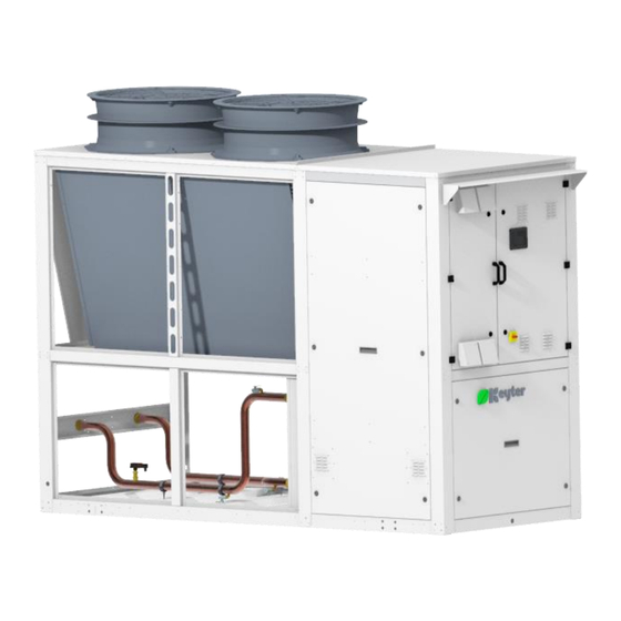
INSTALLATION AND MAINTENANCE MANUAL GENERAL DESCRIPTION KEYTER ZIRAN PRO KWR units are compact water-condensed heat pumps designed to control the water temperature in industrial and air-conditioning applications. In line with our firm commitment to the environment, this range has been specially designed with ➢... - Page 4 TECHNICAL MANUAL Heat pump range Cooling capacity (water I/O 12/7ºC; outdoor air 35ºC): [33 kW – 194 kW] Heating capacity (water I/O 30/35ºC; outdoor air 7ºC DB, 90% RH): [41 kW – 253 kW] The units are made up of one or two refrigerant circuits, with a compressors in each circuit: Series 1 and 2->...
-
Page 5: Coding
TECHNICAL MANUAL CODING K W R 2 100 I V S 4 D K: Air-conditioning range W: Compact air-to-water heat pump R: Heat pump with R290 refrigerant (piston) 2: Build dimensions 100: Nominal power under ARI conditions (cooling if there are several values) I: Type of application (I: Heat pump) V: Type of compressor (N: Inverter piston compressor) S: Hydraulic version:... -
Page 6: Operating Limits
TECHNICAL MANUAL OPERATING LIMITS The operating limits of the ZIRAN PRO units are shown below: Cooling mode: < Blue area: map of the unit's operation at full charge. • T1: Output water temperature (ºC). • T2: Outdoor air temperature DB (ºC). •... -
Page 7: Regulations
TECHNICAL MANUAL REGULATIONS KEYTER complies with all European quality, environmental and eco-efficient design regulations and standards. The units meet the requirements of the following European standards: ISO 9001:2015 Quality Management System, certified by TÜV Rheinland. ISO 14001:2015 Environmental Management System, certified by TÜV Rheinland. Machinery Directive 2006/42/EC, certified by TÜV Rheinland. -
Page 8: Components
COMPONENTS Casing The heat pumps of the KEYTER ZIRAN PRO KWR E range are built as standard with a self- supporting galvanised steel chassis with a high zinc content. Some of the unit's non-structural elements are made of aluminium to reduce the weight. All machine parts are coated with an oven- cured polyester paint treatment. - Page 9 TECHNICAL MANUAL ➢ Series 3 Chassis S-P: Chassis H: ➢ Series 4 Chassis S-P-H: MM_KWR_2306A_EN_EU...
- Page 10 TECHNICAL MANUAL Refrigerant KEYTER KWR units use R290 refrigerant as standard, which has a very low Global Warming Potential. R290: ODP 0, GWP 3 Safety classification: A3 (low toxicity and highly flammable). In any case, the unit must always run with the refrigerant indicated in the nameplate. Full charge of refrigerant ex-works.
- Page 11 TECHNICAL MANUAL Principle of operation of the STO: Safe Torque Off (STO) Standard drive functions linked to the STO 1. The inverter detects the STO selection via a safety-related input or via the PROFIsafe safety communication. 2. The inverter interrupts the power If a motor holding brake is used, the inverter supply to the motor.
- Page 12 TECHNICAL MANUAL Characteristic curves: airflow 50 Hz ATEX axial flow fan for refrigerant gas extraction ATEX axial fan designed to extract refrigerant gas from inside the equipment enclosure in the event of a leak. This fan operates when a leak is detected. In addition, for safety reasons, it will be activated periodically to ensure correct operation.
- Page 13 TECHNICAL MANUAL Heat exchangers The heat exchangers installed in units of the KEYTER KWR series are AISI 316L stainless steel plate heat exchangers brazed with copper and heat insulated. The evaporator-type brazed plate heat exchangers installed as standard include a distributor in the refrigerant inlet channel. It is very important to select and install this correctly to ensure the proper operation of the heat exchanger as an evaporator, to make sure that the biphasic mixture is distributed correctly at the...
- Page 14 TECHNICAL MANUAL Maximum and minimum temperature difference permitted (ºC) Minimum DeltaT Maximum DeltaT Cold water outlet temperature (ºC) These limits are for equipment operating at full load. As a general rule, the filling water should also be previously filtered and treated. Sensors The units feature thermistors to measure the temperature, and pressure transducers to control the unit (see the control manual for more information).
- Page 15 The electrical panel is designed and installed in a separate compartment from the refrigeration circuit. KEYTER ZIRAN PRO KWR units feature a state-of-the-art AQUAMATIX electronic control system. A Climatix HMI user terminal is also included for AQUAMATIX control, as well as an RS485 communication interface for ModBus communication.
-
Page 16: Optional Components
TECHNICAL MANUAL OPTIONAL COMPONENTS Power supply options The standard version operates with a voltage of 400/III/50 Hz + neutral (power supply code 4). For other power supplies, please contact the sales department. Outdoor coil protection Copper/aluminium coils. The KEYTER ZIRAN PRO series has the following options available for Cu/Al outdoor coil protection: Condensing coil with copper tube and aluminium fins, with polyurethane pre-lacquer. - Page 17 TECHNICAL MANUAL Unit enclosure (series 2) No enclosure Closed hydraulic enclosure and coil protection grille Closed hydraulic enclosure Coil protection grille Unit enclosure (series 3, chassis S/P) No enclosure Closed hydraulic enclosure and coil protection grille MM_KWR_2306A_EN_EU...
- Page 18 TECHNICAL MANUAL Closed hydraulic enclosure Coil protection grille Unit enclosure (Series 3, chassis H) No enclosure Closed hydraulic enclosure and coil protection grille Closed hydraulic enclosure MM_KWR_2306A_EN_EU...
- Page 19 TECHNICAL MANUAL Coil protection grille Unit enclosure (series 4) No enclosure Closed hydraulic enclosure and coil protection grille MM_KWR_2306A_EN_EU...
- Page 20 TECHNICAL MANUAL Closed hydraulic enclosure Coil protection grille All panels can be removed in order to access the inside of the unit for maintenance tasks. Both the cooling and hydraulic enclosure panels are available with 10 or 20 mm thick polyurethane insulation or 20 mm thick rock wool sandwich panel.
- Page 21 TECHNICAL MANUAL Enhanced axial EC fans: “V” airflow direction. Screwing depth max. 20 mm. Cable diameter: min. 4 mm, max. 10 mm, Tightening torque: 4±0.6 Nm. Tightening torque 1.5±0.2 Nm. Characteristic curves: airflow 50 Hz Silent Ring nozzle is mounted as standard with this option. MM_KWR_2306A_EN_EU...
- Page 22 TECHNICAL MANUAL Radial EC plug fans: Assembly position: Shaft horizontal (only install support struts vertically, as shown) or rotor on bottom. Cable diameter: min. 4 mm, max. 10 mm, Tightening torque: 2±0.3 Nm. Tightening torque 1.5±0.2 Nm. Fixing holes for FlowGrid. Inlet nozzle with pressure intake tube (factor k:535) Characteristic curves: airflow 50 Hz MM_KWR_2306A_EN_EU...
- Page 23 TECHNICAL MANUAL AxiTop® acoustic diffuser The AxiTop® acoustic diffusion system is available as an accessory mounted at the factory or supplied as a kit, for installations that require efficiency, ultraquiet operation. The AXITOP provides an acoustic diffusion effect that reduces the noise level by between 1 and 3 dB(A) and increases the axial fan efficiency, making it an ideal, efficient and economic solution for installations where noise is a key design parameter, but where efficiency and capacity cannot be compromised.
- Page 24 TECHNICAL MANUAL ATEX centrifugal fan for refrigerant gas extraction ATEX centrifugal fan designed to extract refrigerant gas from inside the equipment enclosure in the event of a leak. This fan allows the leak to be directed to a safe location. This fan operates when a leak is detected.
- Page 25 Recommended for outdoor temperatures of -5ºC or below, and required for outdoor temperatures of -10ºC or below. Hydraulic versions KEYTER ZIRAN PRO KWR units are available in three versions according to their hydraulic elements: S version: standard equipment, without a hydraulic unit.
- Page 26 TECHNICAL MANUAL S version: standard unit, without a hydraulic unit KEYTER KWR units feature a triple protection of the heat exchanger or multi-plate exchanger, respectively, because they come with a flow switch, water anti-freeze protection and freon anti- freeze protection as standard. The water filter is not included as standard, but it can be supplied as an option.
- Page 27 TECHNICAL MANUAL Liquid characteristics: Clean fresh water Temperature limits: (check for extreme conditions) Version with cast-iron impeller, mechanical seal according 24960 (carbon/ceramic/NBR) The motors incorporated in the pumps have the following characteristics: Three-phase motor with nominal powers below 7.5 kW efficiency IE2, and three-phase motors with nominal powers from 7.5 kW efficiency IE3.
- Page 28 TECHNICAL MANUAL The tables below show the operating limits for water temperature and the glycol percentage of KWR units with the standard, high and very high-pressure pump: Pump with standard pressure available: Minimum Maximum Maximum glycol KWR model Pump mechanical seal temperature (ºC) temperature (ºC) Standard version...
-
Page 29: Characteristics Of Natural Refrigerant R290
TECHNICAL MANUAL CHARACTERISTICS OF NATURAL REFRIGERANT R290 Propane, or R-290, is a hydrocarbon used in some cooling units, such as heat pumps, commercial cooling units, etc. When working with hydrocarbons as refrigerants, these must be high-purity hydrocarbons, since any proportion with other impurities, such as sulphur, water, etc., may degrade the installation's lubricating oils, cause compressors to malfunction and break, etc. -
Page 30: General Safety Recommendations
10+10 (kg) Ziran Pro KWR units can therefore be installed in areas with supervised access (b) for not exceeding 10 kg load per circuit or in areas with authorised access. The units are designed and built in compliance with the latest European safety regulations, such as the Spanish and European standard UNE-EN 378:2017, Refrigerating systems and heat pumps. - Page 31 TECHNICAL MANUAL Safety can only be guaranteed if these instructions and the regulation are followed carefully. Otherwise, there is a risk of damage to property and injuries to persons. The unit must only be used according to its design purpose. Any other improper or unintended use will be considered hazardous.
- Page 32 TECHNICAL MANUAL The mains or isolator switch can be locked out. Safety labels on the unit Do not open the electronic pump control module or remove its control elements. Never remove the rotor from the electronic pump. Dismounting the permanent magnet rotor from the electronic pump may be fatal to persons with medical implants.
- Page 33 TECHNICAL MANUAL Use PPE when working on the unit. Goggles, gloves, safety boots, safety ear muffs, suitable clothing and helmet, if necessary. Signs warning about operations with refrigerant: Eye protection: safety goggles or protective goggles against splashed chemicals. In compliance with the EN 166 or ANSI Z87.1 standards. In addition, wear a face shield if there is a risk of contact with splashed and/or sprayed liquids or when in contact with liquids suspended in air.
- Page 34 TECHNICAL MANUAL Do not have parts of the unit containing refrigerant near sources of ignition. No smoking is allowed. Refrigerant leaks can cause: Suffocation caused by the displacement of oxygen in confined work spaces and ▪ narcotic effects or arrhythmia caused by the inhalation of refrigerant. Eye irritation and burns due to splashes or contact with skin.
- Page 35 TECHNICAL MANUAL been tripped because, when the circuit waste is released, such as metal shavings or weld remains, these could fall on the valve seal and then prevent the safety valve from returning to the original position. Components must always be repaired and/or replaced by qualified staff. Please contact KEYTER's Technical Service when the safety valve is tripped to find the root cause for this.
- Page 36 TECHNICAL MANUAL Monoethylene glycol Monoethylene glycol (also known as ethylene glycol) is an organic compound with the formula: CH2OHCH2OH. Ethylene glycol is widely used as an anti-freeze and heat transfer fluid in the automotive industry. It is a transparent, colourless and almost odourless liquid that is completely soluble in water.
-
Page 37: Residual Risks
TECHNICAL MANUAL RESIDUAL RISKS All of the risks derived from the unit's operation cannot be fully eliminated, so it is vital to follow the instructions included in this manual. The unit's residual risks are listed below: ▪ There is a risk of thermal contact with parts of the unit subject to high and low temperatures. -
Page 38: Receiving The Unit
TECHNICAL MANUAL RECEIVING THE UNIT Keep in mind the following considerations upon reception of the unit and before start-up: The unit received corresponds to the specifications included in the order. Compare the data on the nameplate with that in the order. The packaging must be in perfect condition. - Page 39 TECHNICAL MANUAL Always use the refrigerant indicated on the nameplate in its pure state. Avoid using refrigerant blends or other substances. It is the customer's responsibility to ensure that the goods have arrived in perfect condition. ▪ Upon receiving your unit, check that there is no damage either on the unit or its components.
-
Page 40: Storage Conditions
TECHNICAL MANUAL STORAGE CONDITIONS The unit should be stored at its final location. If the unit needs to be stored, make sure that it is stored in a suitable place. The unit contains R290 refrigerant. Keep in mind that this type of refrigerant is denser than air. In the event of leaks, the refrigerant may accumulate close to the ground. -
Page 41: Recommendations For Transport And Lifting
TECHNICAL MANUAL RECOMMENDATIONS FOR TRANSPORT AND LIFTING The unit must be handled with care to prevent damage during transport and when installing it in its final location. Follow these instructions and the indications in the dimensional drawings supplied with the unit: Units must be moved carefully by qualified staff and with the suitable tools. - Page 42 TECHNICAL MANUAL Lifting slings Before lifting the unit, check and make sure that all panels of the enclosure are fastened properly. Lift and lower the unit carefully. Incorrect tilting and handling may damage the unit and affect its operation. MM_KWR_2306A_EN_EU...
-
Page 43: Installation
TECHNICAL MANUAL INSTALLATION The final location of the unit will largely determine the proper functioning of the unit. The customer is responsible for the unit's assembly. The unit must be installed in a place that cannot be easily accessed and must be protected against access of unauthorised staff. - Page 44 TECHNICAL MANUAL Install the unit in a place with good ventilation and away from heat sources. Respect the minimum distances shown on page 139 to guarantee proper access to the components during maintenance and the necessary degree of safety. To guarantee proper operation of the unit and proper access to the components during maintenance, observe the minimum recommended distances on the minimum maintenance distance (page 139) supplied with the unit.
- Page 45 TECHNICAL MANUAL Hydraulic connections The hydraulic connections are shown on the dimensional drawings supplied with the unit. Pay special attention to the input and output water connections (as shown on the drawings) to maintain the correct water flow rate direction. This direction is also shown on the corresponding labels attached to the unit: Hydraulic connections...
- Page 46 TECHNICAL MANUAL Electrical installation To prevent electric shock or damage to the unit, make sure that the disconnection points are open before making the electrical connections. Failure to implement these measures may cause injury to workers. The electrical control panel and power supply connections must be made by qualified staff.
- Page 47 TECHNICAL MANUAL Check the cross-section of the cables to make sure that it complies with the current regulations, according to the operating conditions. Keep in mind the current intensity shown in the technical datasheet. If the unit is three-phase with neutral and ground, check that the installation is equipped with a three-phase network with neutral and ground.
- Page 48 TECHNICAL MANUAL Installing the AxiTop ® diffuser (optional) Axitop is a diffuser installed directly on the axial fan grille, with a 800 and 910(A) diameter and which reduces the noise levels by 1 to 3 dB(A). It can also be used to improve the fan performance (by up to 9%).
- Page 49 TECHNICAL MANUAL Position of the fan with the support ring, making sure that the press is bolted in the final mounting position and facing downwards (this also applies to the vertical mounting process). Fit and tighten the screws. Next, connect the terminal box, making sure that the wiring order is respected. In the case of 150 motors (910 mm diameter), install the cooling pipe (see image below).
- Page 50 TECHNICAL MANUAL Finally, mount the diffuser, as shown in the image below. If the diffuser is removed, mount it so it can be fitted on the fan. Left: diffuser mounted. Right: internal diffuser dismounted and placed on the motor Left: exterior diffuser assembly. Right: mounting the outer diffuser on the motor Left: mounting the protective grille.
-
Page 51: Start-Up
TECHNICAL MANUAL START-UP The start-up procedure must be carried out by qualified technicians, with the corresponding qualification certificates in compliance with the local regulations. No special equipment or accessories are needed. Only the standard equipment and accessories used by a qualified technician are required to start the unit according to UNE EN 378-4:2017. - Page 52 TECHNICAL MANUAL exchanger. Take this into account in the case of version S units installed with the pump at the installation. Install a filter in the water circuit, upstream of the heat exchanger. This filter must stop all ▪ particles larger than 1 mm in diameter and must be installed at least 1 m away from the heat exchanger inlet.
- Page 53 TECHNICAL MANUAL An unstable process can also cause the evaporation temperature to fluctuate, with the potential risk of freezing the evaporator. Therefore, it is necessary to check that the selected values when sizing the installation are within those included in the chart, which shows the work points required to run plate exchangers, in relation to the output temperature of the exchanger and its difference in temperature (DT).
- Page 54 TECHNICAL MANUAL Start-up The start-up and performance tests must be carried out after applying the thermal load. Check that the flow rate of water circulating through the heat exchanger is as required. Connect the power supply source and turn on the system. ▪...
-
Page 55: Start-Up And Verification Report
TECHNICAL MANUAL START-UP AND VERIFICATION REPORT CUSTOMER AND SITE DATA Customer: Contact person: Contact number: Site management: Models: Serial no.: Date: Date requested for the start-up: GENERAL CONDITIONS Keep in mind the indications on page 51, in addition to the following: The following preliminary tasks must be carried out prior to start-up: ▪... - Page 56 TECHNICAL MANUAL INSPECTION CHECKLIST On-site Ref: MODEL Nº CIRCUITS SERIAL NO. Nº COMPRESSORS REFRIGERANT REGULATION/REV. PREPARED BY DATE OP. MODE/SETPOINT PHASE RELAY DIRTY PRESSURE SWITCH FILTER FREECOOLING TYPE FLOW RATE CONTROL OPTIONS ELECTRICAL CHECK GROUP NO. 1 GROUP NO. 2 GROUP NO.
- Page 57 TECHNICAL MANUAL On-site checks 1. Reset all meters to 0 2. Check that the maintenance records have no errors 3. Check that the unit has been accessed properly 4. Check that there are no surface defects on the unit 5. Unit documents (manuals, wiring diagram, layout, technical datasheet, CE marking) Remarks regarding the performance tests: MM_KWR_2306A_EN_EU...
-
Page 58: Maintenance
TECHNICAL MANUAL MAINTENANCE The warranty will only be valid after a maintenance contract is signed with a qualified specialist company. The maintenance contract must be signed so it is effective as of the date of commissioning. The maintenance tasks must be carried out on the unit. The maintenance tasks must be carried out by qualified staff, even after the end of the warranty period. - Page 59 TECHNICAL MANUAL Cooling components Early detection of R290 refrigerant leaks is essential to prevent risk situations. It is important to perform periodic inspections and preventive maintenance to ensure the correct condition of piping and connections. Every three months, check the degree of sealing of the connections in the refrigerant circuit, using a suitable leak detector for the refrigerant gas in the unit.
- Page 60 TECHNICAL MANUAL Replacement coils Clean the tube and fin exchangers or coils to guarantee the proper functioning of this heat exchanger and, therefore, the optimal performance of the unit. Coils must be cleaned once every three months. However, in the case of installations with a high dust content, they must be cleaned at least once a month.
- Page 61 TECHNICAL MANUAL Make sure that the regular service inspections are carried out to guarantee that the unit performs as expected in terms of reliability and in compliance with the current local regulations. The following maintenance tasks must be carried out on a regular basis to prevent problems in the compressor associated with the system: Check that the safety devices are working properly and adjusted as required.
- Page 62 TECHNICAL MANUAL Avoid rapid changes in the suction pressure. There is a risk of causing friction due to a • high gas discharge of the refrigerant and overheating of unstable suction gas. Avoid rapid changes in the condensation pressure. There is a risk of forming heavy foam •...
- Page 63 TECHNICAL MANUAL In any case, clean the water filter every three months and heed the corresponding warnings for the LP water circuits. Heat exchanger Check that the heat exchanger's water side is clean. To do so, measure the pressure drop on the water side once a week or measure the input and output refrigerant temperatures of the heat exchanger and compare them with the condensation or evaporation pressures.
- Page 64 TECHNICAL MANUAL Resistance of the heat exchanger to corrosion In general, the filling water inlet should be filtered and treated beforehand. These units are designed for closed water circuits. The main component of the hydraulic circuit is the heat exchanger. There might be problems caused by corrosion in this exchanger, which could damage it if the water does not have the suitable characteristics.
- Page 65 TECHNICAL MANUAL This type of shell and tube heat exchanger is recommended in industrial applications where the water may contain some dirt or there is an open circuit, although it is very important to monitor the water conditions to prevent corrosion issues in the hydraulic circuit if the water is not suitable. It is important to follow the general guidelines to make sure that the filling water is previously filtered and treated.
- Page 66 TECHNICAL MANUAL Preventing corrosion on copper Low oxygen concentration. If it is less than 0.1 ppm, no corrosion will be formed due to pitting. The high content in HCO3 - & Cl ions reduces the risk of corrosion. A high SO4 2- and NO3 ion content increases the risk of corrosion. The recommended pH is 6.5 <pH <9.5.
- Page 67 TECHNICAL MANUAL Exercise due caution in reverse osmosis water applications, since these have extremely aggressive pH levels for metallic minerals. All of these assumptions are not contemplated in the standard applications of the unit. Please contact the factory for more information. Failing to observe any of the recommendations indicated in this document to maintain the exchanger water within the values indicated in the above table will void the warranty of the unit.
- Page 68 TECHNICAL MANUAL respirators, gloves and boots when handling and using chemical products. Immediately rinse liquids or particles splashed onto the skin with water. In case of liquids splashed into the eyes, rinse with fresh water and seek medical attention. Never inject these types of liquids. Propylene glycol: Propylene glycol (MPG) can be used instead of monoethylene glycol (MED) in applications that require greater safety, such as food applications.
-
Page 69: Troubleshooting
TECHNICAL MANUAL TROUBLESHOOTING SYMPTOM POSSIBLE CAUSE CORRECTIVE ACTION Not connected to the mains. Check the connection of the power supply source. Main switch open. Close the main switch. Contactor jammed in the open Check and, if needed, replace. position. The PCB is not connected to Check thermal-magnetic switches... - Page 70 TECHNICAL MANUAL The pressure transducers are not Calibrate the pressure transducers and the condensing working properly. pressure regulation system, if installed. In the case of thermostatic pressure valves, check that The expansion valve is not the valve opens by heating the bulb manually and working properly.
-
Page 71: Recommendations When Disassembling The Unit
TECHNICAL MANUAL RECOMMENDATIONS WHEN DISASSEMBLING THE UNIT When the unit has reached the end of its service life and needs to be removed from service, please keep in mind that the unit contains flammable R290 refrigerant. When units are transported without the original packaging, the refrigerant circuit may be damaged and refrigerant may be released. -
Page 72: End Of The Unit's Service Life
TECHNICAL MANUAL END OF THE UNIT'S SERVICE LIFE At the end of the unit's service life, all electronic and electrical waste must be managed in compliance with the WEEE regulation (Waste Electrical and Electronic Equipment), European Directive 2012/19/EU. Such waste must be removed and recycled by authorised waste managers, according to the type of waste. -
Page 73: Dimensional Drawings
TECHNICAL MANUAL DIMENSIONAL DRAWINGS SERIES 1 CHASSIS S/P/H ELECTRICAL PANEL CUADRO ELÉCTRICO MAIN SWITCH INTERRUPTOR GENERAL REMOVABLE TRANSPORT SUPPORTS SOPORTES DESMONTABLES REMOVABLE LIFTING BRACKETS PARA TRANSPORTE GARRAS DE ELEVACIÓN DESMONTABLES SAFETY VALVE VÁLVULA DE SEGURIDAD MM_KWR_2306A_EN_EU... - Page 74 INSTALLATION AND MAINTENANCE MANUAL OPTIONS SILENT RING TOBERA EXTERIOR CURVA SILENT RING + AXITOP TOBERA EXTERIOR CURVA + AXITOP MM_KWR_2306A_EN_EU...
- Page 75 INSTALLATION AND MAINTENANCE MANUAL COIL PROTECTION GRID REJILLAS DE PROTECCIÓN DE BATERÍA FULLY CLOSED SHEET COMPARTMENT COMPARTIMENTO DE CHAPA COMPLETAMENTE CERRADO MM_KWR_2306A_EN_EU...
- Page 76 INSTALLATION AND MAINTENANCE MANUAL P HYDRAULIC VERSION VERSIÓN HIDRÁULICA P SINGLE PUMP RESERVE PUMP BOMBA SIMPLE BOMBA DE RESERVA H HYDRAULIC VERSION VERSIÓN HIDRÁULICA H SINGLE PUMP RESERVE PUMP BOMBA SIMPLE BOMBA DE RESERVA MM_KWR_2306A_EN_EU...
- Page 77 INSTALLATION AND MAINTENANCE MANUAL PARTIAL HEAT RECOVERY RECUPERACIÓN PARCIAL A DETAIL / DETALLE A SCALE 1:25 / ESCALA 1:25 B DETAIL / DETALLE B SCALE 1:25 / ESCALA 1:25 SEE DETAIL A SEE DETAIL B TOTAL HEAT RECOVERY RECUPERACIÓN TOTAL C DETAIL / DETALLE C SCALE 1:25 / ESCALA 1:25 D DETAIL / DETALLE D...
- Page 78 INSTALLATION AND MAINTENANCE MANUAL FREE-COOLING FREE-COOLING S VERSION / VERSIÓN S P VERSION / VERSIÓN P FREE-COOLING H VERSION / VERSIÓN H MM_KWR_2306A_EN_EU...
- Page 79 INSTALLATION AND MAINTENANCE MANUAL HYDRAULIC CONNECTION DETAILS S/P VERSIONS / VERSIONES S/P WATER OUTLET WATER INLET GAS THREAD Ø A EXTERIOR GAS THREAD Ø A EXTERIOR SALIDA DE AGUA ENTRADA DE AGUA ROSCA GAS Ø A EXTERIOR ROSCA GAS Ø A EXTERIOR HYDRAULIC CONNECTIONS MAIN CIRCUIT CONEXIONES HIDRÁULICAS CIRCUITO PRINCIPAL CONNECTIONS...
- Page 80 INSTALLATION AND MAINTENANCE MANUAL H VERSION / VERSIÓN H WATER INLET WATER OUTLET GAS THREAD Ø A EXTERIOR GAS THREAD Ø A EXTERIOR ENTRADA DE AGUA SALIDA DE AGUA ROSCA GAS Ø A EXTERIOR ROSCA GAS Ø A EXTERIOR HYDRAULIC CONNECTIONS MAIN CIRCUIT CONEXIONES HIDRÁULICAS CIRCUITO PRINCIPAL CONNECTIONS CONNECTION DIMENSIONS...
- Page 81 INSTALLATION AND MAINTENANCE MANUAL PARTIAL HEAT RECOVERY RECUPERACIÓN PARCIAL WATER INLET WATER OUTLET GAS THREAD Ø B EXTERIOR GAS THREAD Ø B EXTERIOR ENTRADA DE AGUA SALIDA DE AGUA ROSCA GAS Ø B EXTERIOR ROSCA GAS Ø B EXTERIOR HYDRAULIC CONNECTIONS PARTIAL HEAT RECOVERY CONEXIONES HIDRÁULICAS RECUPERACIÓN PARCIAL DE CALOR CONNECTIONS CONNECTION DIMENSIONS...
- Page 82 INSTALLATION AND MAINTENANCE MANUAL ELECTRICAL SYSTEM DETAILS AND DRAINS DRAIN GAS THREAD ELECTRICAL INLET 1 1/4" EXTERIOR ACOMETIDA ELÉCTRICA DESAGÜES ROSCA GAS 1 1/4" EXTERIOR ATEX VENTILATION GRILLES E DETAIL / DETALLE E F DETAIL / DETALLE F SCALE 1:25 / ESCALA 1:25 SCALE 1:25 / ESCALA 1:25 SEE DETAIL F SEE DETAIL E...
- Page 83 INSTALLATION AND MAINTENANCE MANUAL DIMENSIONS FOR TRANSPORT TRANSPORT HEIGHT OPTIONAL ALTURA DE TRANSPORTE OPCIONAL H (mm) STANDARD/ESTÁNDAR* 2750 AXITOP** 2880 TRANSPORT LENGHT VERSION LONGITUD DE TRANSPORTE VERSIÓN L (mm) S/P/H VERSIONS / VERSIONES S/P/H 2740 (*) Silent ring has the same height. / Tobera exterior curva tiene la misma altura. (**) AxiTop is a removable part.
- Page 84 INSTALLATION AND MAINTENANCE MANUAL WEIGHT DISTRIBUTION VERSION S 6 x M12 SUPPORTS FOR SILENTBLOCKS 6 X M12 ANTIVIBRATORIOS EMPTY WEIGHT DISTRIBUTION / DISTRIBUCIÓN DE PESOS EN VACÍO GRAVITY CENTER SUPPORTS (kg) WEIGHT (kg) MODEL CENTRO DE GRAVEDAD REACCIONES (kg) PESO (kg) MODELO XG (mm) YG (mm)
- Page 85 INSTALLATION AND MAINTENANCE MANUAL VERSION P 6 x M12 SUPPORTS FOR SILENTBLOCKS 6 X M12 ANTIVIBRATORIOS EMPTY WEIGHT DISTRIBUTION / DISTRIBUCIÓN DE PESOS EN VACÍO GRAVITY CENTER SUPPORTS (kg) WEIGHT (kg) MODEL CENTRO DE GRAVEDAD REACCIONES (kg) PESO (kg) MODELO XG (mm) YG (mm) TOTAL...
- Page 86 INSTALLATION AND MAINTENANCE MANUAL VERSION H 6 x M12 SUPPORTS FOR SILENTBLOCKS 6 X M12 ANTIVIBRATORIOS EMPTY WEIGHT DISTRIBUTION / DISTRIBUCIÓN DE PESOS EN VACÍO GRAVITY CENTER SUPPORTS (kg) WEIGHT (kg) MODEL CENTRO DE GRAVEDAD REACCIONES (kg) PESO (kg) MODELO XG (mm) YG (mm) TOTAL...
- Page 87 INSTALLATION AND MAINTENANCE MANUAL INCREASED WEIGHT DUE TO OPTIONAL ACCESSORIES INSTALLED 6xM12SUPPORTS FOR SILENTBLOCKS 6 X M12 ANTIVIBRATORIOS WEIGHT INCREASE BY OPTIONALS / INCREMENTO DE PESOS POR OPCIONALES SUPPORTS (kg) WEIGHT (kg) OPTIONALS REACCIONES (kg) PESO (kg) OPCIONALES TOTAL AXITOP + 4.0 +3.7 +0.1...
- Page 88 INSTALLATION AND MAINTENANCE MANUAL LIFTING STRUCTURE VERSIONS S/P/H MM_KWR_2306A_EN_EU...
- Page 89 INSTALLATION AND MAINTENANCE MANUAL SERIES 2 VERSIONS S/P/H ELECTRICAL PANEL CUADRO ELÉCTRICO MAIN SWITCH INTERRUPTOR GENERAL REMOVABLE LIFTING BRACKETS REMOVABLE TRANSPORT SUPPORTS GARRAS DE ELEVACIÓN DESMONTABLES SOPORTES DESMONTABLES PARA TRANSPORTE SAFETY VALVE VÁLVULA DE SEGURIDAD MM_KWR_2306A_EN_EU...
- Page 90 INSTALLATION AND MAINTENANCE MANUAL OPTIONS SILENT RING TOBERA EXTERIOR CURVA SILENT RING + AXITOP TOBERA EXTERIOR CURVA + AXITOP MM_KWR_2306A_EN_EU...
- Page 91 INSTALLATION AND MAINTENANCE MANUAL COIL PROTECTION GRID REJILLAS DE PROTECCIÓN DE BATERÍA FULLY CLOSED SHEET COMPARTMENT COMPARTIMENTO DE CHAPA COMPLETAMENTE CERRADO MM_KWR_2306A_EN_EU...
- Page 92 INSTALLATION AND MAINTENANCE MANUAL P HYDRAULIC VERSION VERSIÓN HIDRÁULICA P SINGLE PUMP RESERVE PUMP BOMBA SIMPLE BOMBA DE RESERVA H HYDRAULIC VERSION VERSIÓN HIDRÁULICA H SINGLE PUMP RESERVE PUMP BOMBA SIMPLE BOMBA DE RESERVA MM_KWR_2306A_EN_EU...
- Page 93 INSTALLATION AND MAINTENANCE MANUAL PARTIAL HEAT RECOVERY RECUPERACIÓN PARCIAL A DETAIL / DETALLE A SCALE 1:25 / ESCALA 1:25 B DETAIL / DETALLE B SCALE 1:25 / ESCALA 1:25 SEE DETAIL A SEE DETAIL B TOTAL HEAT RECOVERY RECUPERACIÓN TOTAL C DETAIL / DETALLE C SCALE 1:25 / ESCALA 1:25 D DETAIL / DETALLE D...
- Page 94 INSTALLATION AND MAINTENANCE MANUAL FREE-COOLING FREE-COOLING S VERSION / VERSIÓN S P VERSION / VERSIÓN P FREE-COOLING H VERSION / VERSIÓN H MM_KWR_2306A_EN_EU...
- Page 95 INSTALLATION AND MAINTENANCE MANUAL HYDRAULIC CONNECTION DETAILS S/P VERSIONS / VERSIONES S/P WATER OUTLET WATER INLET GAS THREAD Ø A EXTERIOR GAS THREAD Ø A EXTERIOR SALIDA DE AGUA ENTRADA DE AGUA ROSCA GAS Ø A EXTERIOR ROSCA GAS Ø A EXTERIOR HYDRAULIC CONNECTIONS MAIN CIRCUIT CONEXIONES HIDRÁULICAS CIRCUITO PRINCIPAL CONNECTIONS...
- Page 96 INSTALLATION AND MAINTENANCE MANUAL H VERSION / VERSIÓN H WATER OUTLET WATER INLET GAS THREAD Ø A EXTERIOR GAS THREAD Ø A EXTERIOR SALIDA DE AGUA ENTRADA DE AGUA ROSCA GAS Ø A EXTERIOR ROSCA GAS Ø A EXTERIOR HYDRAULIC CONNECTIONS MAIN CIRCUIT CONEXIONES HIDRÁULICAS CIRCUITO PRINCIPAL CONNECTIONS CONNECTION DIMENSIONS...
- Page 97 INSTALLATION AND MAINTENANCE MANUAL PARTIAL HEAT RECOVERY RECUPERACIÓN PARCIAL WATER OUTLET WATER INLET GAS THREAD Ø B EXTERIOR GAS THREAD Ø B EXTERIOR SALIDA DE AGUA ENTRADA DE AGUA ROSCA GAS Ø B EXTERIOR ROSCA GAS Ø B EXTERIOR HYDRAULIC CONNECTIONS PARTIAL HEAT RECOVERY CONEXIONES HIDRÁULICAS RECUPERACIÓN PARCIAL DE CALOR CONNECTIONS CONNECTION DIMENSIONS...
- Page 98 INSTALLATION AND MAINTENANCE MANUAL ELECTRICAL SYSTEM DETAILS AND DRAINS DRAIN GAS THREAD ELECTRICAL INLET 1 1/4" EXTERIOR ACOMETIDA ELÉCTRICA DESAGÜES ROSCA GAS 1 1/4" EXTERIOR ATEX VENTILATION GRILLES F DETAIL / DETALLE F E DETAIL / DETALLE E SCALE 1:25 / ESCALA 1:25 SCALE 1:25 / ESCALA 1:25 SEE DETAIL F SEE DETAIL E...
- Page 99 INSTALLATION AND MAINTENANCE MANUAL DIMENSIONS FOR TRANSPORT TRANSPORT HEIGHT OPTIONAL ALTURA DE TRANSPORTE OPCIONAL H (mm) STANDARD/ESTÁNDAR 2750 AXITOP* 2880 TRANSPORT LENGHT VERSION LONGITUD DE TRANSPORTE VERSIÓN L (mm) S/P/H VERSIONS / VERSIONES S/P/H 3340 (*) AxiTop is a removable part. / AxiTop es una pieza desmontable. MM_KWR_2306A_EN_EU...
- Page 100 INSTALLATION AND MAINTENANCE MANUAL WEIGHT DISTRIBUTION VERSION S 6 x M12 SUPPORTS FOR SILENTBLOCKS 6 X M12 ANTIVIBRATORIOS EMPTY WEIGHT DISTRIBUTION / DISTRIBUCIÓN DE PESOS EN VACÍO GRAVITY CENTER SUPPORTS (kg) WEIGHT (kg) MODEL CENTRO DE GRAVEDAD REACCIONES (kg) PESO (kg) MODELO XG (mm) YG (mm)
- Page 101 INSTALLATION AND MAINTENANCE MANUAL VERSION P 6 x M12 SUPPORTS FOR SILENTBLOCKS 6 X M12 ANTIVIBRATORIOS EMPTY WEIGHT DISTRIBUTION / DISTRIBUCIÓN DE PESOS EN VACÍO GRAVITY CENTER SUPPORTS (kg) WEIGHT (kg) MODEL CENTRO DE GRAVEDAD REACCIONES (kg) PESO (kg) MODELO XG (mm) YG (mm) TOTAL...
- Page 102 INSTALLATION AND MAINTENANCE MANUAL VERSION H 6 x M12 SUPPORTS FOR SILENTBLOCKS 6 X M12 ANTIVIBRATORIOS EMPTY WEIGHT DISTRIBUTION / DISTRIBUCIÓN DE PESOS EN VACÍO GRAVITY CENTER SUPPORTS (kg) WEIGHT (kg) MODEL CENTRO DE GRAVEDAD REACCIONES (kg) PESO (kg) MODELO XG (mm) YG (mm) TOTAL...
- Page 103 INSTALLATION AND MAINTENANCE MANUAL INCREASED WEIGHT DUE TO OPTIONAL ACCESSORIES INSTALLED 6 x M12 SUPPORTS FOR SILENTBLOCKS 6 X M12 ANTIVIBRATORIOS WEIGHT INCREASE BY OPTIONALS / INCREMENTO DE PESOS POR OPCIONALES SUPPORTS (kg) WEIGHT (kg) OPTIONALS REACCIONES (kg) PESO (kg) OPCIONALES TOTAL AXITOP...
- Page 104 INSTALLATION AND MAINTENANCE MANUAL LIFTING STRUCTURE VERSIONS S/P/H MM_KWR_2306A_EN_EU...
- Page 105 INSTALLATION AND MAINTENANCE MANUAL SERIES 3 VERSIONS S/P ELECTRICAL PANEL CUADRO ELÉCTRICO MAIN SWITCH INTERRUPTOR GENERAL REMOVABLE LIFTING BRACKETS GARRAS DE ELEVACIÓN DESMONTABLES REMOVABLE TRANSPORT SUPPORTS SOPORTES DESMONTABLES PARA TRANSPORTE SAFETY VALVES VÁLVULAS DE SEGURIDAD MM_KWR_2306A_EN_EU...
- Page 106 INSTALLATION AND MAINTENANCE MANUAL VERSION H ELECTRICAL PANEL CUADRO ELÉCTRICO MAIN SWITCH INTERRUPTOR GENERAL REMOVABLE LIFTING BRACKETS REMOVABLE TRANSPORT SUPPORTS GARRAS DE ELEVACIÓN DESMONTABLES SOPORTES DESMONTABLES PARA TRANSPORTE SAFETY VALVES VÁLVULAS DE SEGURIDAD MM_KWR_2306A_EN_EU...
- Page 107 INSTALLATION AND MAINTENANCE MANUAL OPTIONS SILENT RING TOBERA EXTERIOR CURVA SILENT RING + AXITOP TOBERA EXTERIOR CURVA + AXITOP MM_KWR_2306A_EN_EU...
- Page 108 INSTALLATION AND MAINTENANCE MANUAL COIL PROTECTION GRID REJILLAS DE PROTECCIÓN DE BATERÍA FULLY CLOSED SHEET COMPARTMENT COMPARTIMENTO DE CHAPA COMPLETAMENTE CERRADO MM_KWR_2306A_EN_EU...
- Page 109 INSTALLATION AND MAINTENANCE MANUAL P HYDRAULIC VERSION VERSIÓN HIDRÁULICA P SINGLE PUMP RESERVE PUMP BOMBA SIMPLE BOMBA DE RESERVA H HYDRAULIC VERSION VERSIÓN HIDRÁULICA H SINGLE PUMP RESERVE PUMP BOMBA SIMPLE BOMBA DE RESERVA MM_KWR_2306A_EN_EU...
- Page 110 INSTALLATION AND MAINTENANCE MANUAL PARTIAL HEAT RECOVERY RECUPERACIÓN PARCIAL A DETAIL / DETALLE A SCALE 1:25 / ESCALA 1:25 B DETAIL / DETALLE B SCALE 1:25 / ESCALA 1:25 SEE DETAIL A SEE DETAIL B TOTAL HEAT RECOVERY RECUPERACIÓN TOTAL C DETAIL / DETALLE C SCALE 1:25 / ESCALA 1:25 D DETAIL / DETALLE D...
- Page 111 INSTALLATION AND MAINTENANCE MANUAL FREE-COOLING S VERSION / VERSIÓN S FREE-COOLING P VERSION / VERSIÓN P MM_KWR_2306A_EN_EU...
- Page 112 INSTALLATION AND MAINTENANCE MANUAL HYDRAULIC CONNECTION DETAILS S/P VERSIONS / VERSIONES S/P WATER OUTLET WATER INLET FLANGE Ø A FLANGE Ø A SALIDA DE AGUA ENTRADA DE AGUA BRIDA Ø A BRIDA Ø A HYDRAULIC CONNECTIONS MAIN CIRCUIT CONEXIONES HIDRÁULICAS CIRCUITO PRINCIPAL CONNECTIONS CONNECTION DIMENSIONS DIAMETER...
- Page 113 INSTALLATION AND MAINTENANCE MANUAL H VERSION / VERSIÓN H WATER INLET WATER OUTLET FLANGE Ø A FLANGE Ø A ENTRADA DE AGUA SALIDA DE AGUA BRIDA Ø A BRIDA Ø A HYDRAULIC CONNECTIONS MAIN CIRCUIT CONEXIONES HIDRÁULICAS CIRCUITO PRINCIPAL CONNECTIONS CONNECTION DIMENSIONS DIAMETER MODEL...
- Page 114 INSTALLATION AND MAINTENANCE MANUAL PARTIAL HEAT RECOVERY RECUPERACIÓN PARCIAL WATER INLET WATER OUTLET FLANGE Ø B FLANGE Ø B ENTRADA DE AGUA SALIDA DE AGUA BRIDA Ø B BRIDA Ø B HYDRAULIC CONNECTIONS PARTIAL HEAT RECOVERY CONEXIONES HIDRÁULICAS RECUPERACIÓN PARCIAL DE CALOR CONNECTIONS CONNECTION DIMENSIONS DIAMETER...
- Page 115 INSTALLATION AND MAINTENANCE MANUAL ELECTRICAL SYSTEM DETAILS AND DRAINS DRAIN GAS THREAD ELECTRICAL INLET 1 1/4" EXTERIOR ACOMETIDA ELÉCTRICA DESAGÜES ROSCA GAS 1 1/4" EXTERIOR ATEX VENTILATION GRILLES E DETAIL / DETALLE E SCALE 1:25 / ESCALA 1:25 F DETAIL / DETALLE F SCALE 1:25 / ESCALA 1:25 SEE DETAIL F SEE DETAIL E...
- Page 116 INSTALLATION AND MAINTENANCE MANUAL DIMENSIONS FOR TRANSPORT TRANSPORT HEIGHT OPTIONAL ALTURA DE TRANSPORTE OPCIONAL H (mm) STANDARD/ESTÁNDAR 2750 AXITOP* 2880 TRANSPORT LENGHT VERSION LONGITUD DE TRANSPORTE VERSIÓN L (mm) S/P VERSIONS / VERSIONES S/P 4440 H VERSION / VERSIÓN H 5040 (*) AxiTop is a removable part.
- Page 117 INSTALLATION AND MAINTENANCE MANUAL WEIGHT DISTRIBUTION VERSION S 8 x M12 SUPPORTS FOR SILENTBLOCKS 8 X M12 ANTIVIBRATORIOS EMPTY WEIGHT DISTRIBUTION / DISTRIBUCIÓN DE PESOS EN VACÍO GRAVITY CENTER SUPPORTS (kg) WEIGHT (kg) MODEL CENTRO DE GRAVEDAD REACCIONES (kg) PESO (kg) MODELO XG (mm) YG (mm)
- Page 118 INSTALLATION AND MAINTENANCE MANUAL VERSION P 8 x M12 SUPPORTS FOR SILENTBLOCKS 8 X M12 ANTIVIBRATORIOS EMPTY WEIGHT DISTRIBUTION / DISTRIBUCIÓN DE PESOS EN VACÍO GRAVITY CENTER SUPPORTS (kg) WEIGHT (kg) MODEL CENTRO DE GRAVEDAD REACCIONES (kg) PESO (kg) MODELO XG (mm) YG (mm) TOTAL...
- Page 119 INSTALLATION AND MAINTENANCE MANUAL VERSION H 8 x M12 SUPPORTS FOR SILENTBLOCKS 8 X M12 ANTIVIBRATORIOS EMPTY WEIGHT DISTRIBUTION / DISTRIBUCIÓN DE PESOS EN VACÍO GRAVITY CENTER SUPPORTS (kg) WEIGHT (kg) MODEL CENTRO DE GRAVEDAD REACCIONES (kg) PESO (kg) MODELO XG (mm) YG (mm) TOTAL...
- Page 120 INSTALLATION AND MAINTENANCE MANUAL INCREASED WEIGHT DUE TO OPTIONAL ACCESSORIES INSTALLED 8 x M12 SUPPORTS FOR SILENTBLOCKS 8 X M12 ANTIVIBRATORIOS WEIGHT INCREASE BY OPTIONALS / INCREMENTO DE PESOS POR OPCIONALES SUPPORTS (kg) WEIGHT (kg) OPTIONALS REACCIONES (kg) PESO (kg) OPCIONALES TOTAL AXITOP...
- Page 121 INSTALLATION AND MAINTENANCE MANUAL LIFTING STRUCTURE VERSIONS S/P MM_KWR_2306A_EN_EU...
- Page 122 INSTALLATION AND MAINTENANCE MANUAL VERSION H MM_KWR_2306A_EN_EU...
- Page 123 INSTALLATION AND MAINTENANCE MANUAL SERIES 4 VERSIONS S/P/H ELECTRICAL PANEL CUADRO ELÉCTRICO MAIN SWITCH INTERRUPTOR GENERAL REMOVABLE LIFTING BRACKETS REMOVABLE TRANSPORT SUPPORTS GARRAS DE ELEVACIÓN DESMONTABLES SOPORTES DESMONTABLES PARA TRANSPORTE SAFETY VALVES VÁLVULAS DE SEGURIDAD MM_KWR_2306A_EN_EU...
- Page 124 INSTALLATION AND MAINTENANCE MANUAL OPTIONS SILENT RING TOBERA EXTERIOR CURVA SILENT RING + AXITOP TOBERA EXTERIOR CURVA + AXITOP MM_KWR_2306A_EN_EU...
- Page 125 INSTALLATION AND MAINTENANCE MANUAL COIL PROTECTION GRID REJILLAS DE PROTECCIÓN DE BATERÍA FULLY CLOSED SHEET COMPARTMENT COMPARTIMENTO DE CHAPA COMPLETAMENTE CERRADO MM_KWR_2306A_EN_EU...
- Page 126 INSTALLATION AND MAINTENANCE MANUAL P HYDRAULIC VERSION VERSIÓN HIDRÁULICA P SINGLE PUMP RESERVE PUMP BOMBA SIMPLE BOMBA DE RESERVA H HYDRAULIC VERSION VERSIÓN HIDRÁULICA H SINGLE PUMP RESERVE PUMP BOMBA SIMPLE BOMBA DE RESERVA MM_KWR_2306A_EN_EU...
- Page 127 INSTALLATION AND MAINTENANCE MANUAL PARTIAL HEAT RECOVERY RECUPERACIÓN PARCIAL A DETAIL / DETALLE A SCALE 1:25 / ESCALA 1:25 B DETAIL / DETALLE B SCALE 1:25 / ESCALA 1:25 SEE DETAIL B SEE DETAIL A TOTAL HEAT RECOVERY RECUPERACIÓN TOTAL C DETAIL / DETALLE C SCALE 1:25 / ESCALA 1:25 D DETAIL / DETALLE D...
- Page 128 INSTALLATION AND MAINTENANCE MANUAL FREE-COOLING S VERSION / VERSIÓN S FREE-COOLING P VERSION / VERSIÓN P MM_KWR_2306A_EN_EU...
- Page 129 INSTALLATION AND MAINTENANCE MANUAL HYDRAULIC CONNECTION DETAILS S/P VERSIONS / VERSIONES S/P WATER OUTLET WATER INLET FLANGE Ø A FLANGE Ø A SALIDA DE AGUA ENTRADA DE AGUA BRIDA Ø A BRIDA ØA HYDRAULIC CONNECTIONS MAIN CIRCUIT CONEXIONES HIDRÁULICAS CIRCUITO PRINCIPAL CONNECTIONS DIAMETER CONNECTION DIMENSIONS...
- Page 130 INSTALLATION AND MAINTENANCE MANUAL H VERSION / VERSIÓN H WATER INLET WATER OUTLET FLANGE Ø A FLANGE Ø A ENTRADA DE AGUA SALIDA DE AGUA BRIDA Ø A BRIDA Ø A HYDRAULIC CONNECTIONS MAIN CIRCUIT CONEXIONES HIDRÁULICAS CIRCUITO PRINCIPAL CONNECTIONS CONNECTION DIMENSIONS DIAMETER MODEL...
- Page 131 INSTALLATION AND MAINTENANCE MANUAL PARTIAL HEAT RECOVERY RECUPERACIÓN PARCIAL WATER OUTLET WATER INLET FLANGE Ø B FLANGE Ø B SALIDA DE AGUA ENTRADA DE AGUA BRIDA Ø B BRIDA Ø B HYDRAULIC CONNECTIONS PARTIAL HEAT RECOVERY CONEXIONES HIDRÁULICAS RECUPERACIÓN PARCIAL DE CALOR CONNECTIONS CONNECTION DIMENSIONS DIAMETER...
- Page 132 INSTALLATION AND MAINTENANCE MANUAL ELECTRICAL SYSTEM DETAILS AND DRAINS ELECTRICAL INLET ACOMETIDA ELÉCTRICA DRAIN GAS THREAD 1 1/4" EXTERIOR DESAGÜES ROSCA GAS 1 1/4" EXTERIOR ATEX VENTILATION GRILLES E DETAIL / DETALLE E SCALE 1:25 / ESCALA 1:25 F DETAIL / DETALLE F SCALE 1:25 / ESCALA 1:25 SEE DETAIL F SEE DETAIL E...
- Page 133 INSTALLATION AND MAINTENANCE MANUAL DIMENSIONS FOR TRANSPORT TRANSPORT HEIGHT OPTIONAL ALTURA DE TRANSPORTE OPCIONAL H (mm) STANDARD/ESTÁNDAR 2750 AXITOP* 2880 TRANSPORT LENGHT VERSION LONGITUD DE TRANSPORTE VERSIÓN L (mm) S/P/H VERSIONS / VERSIONES S/P/H 5450 (*) AxiTop is a removable part. / AxiTop es una pieza desmontable. MM_KWR_2306A_EN_EU...
- Page 134 INSTALLATION AND MAINTENANCE MANUAL WEIGHT DISTRIBUTION VERSION S 8 x M12 SUPPORTS FOR SILENTBLOCKS 8 X M12 ANTIVIBRATORIOS EMPTY WEIGHT DISTRIBUTION / DISTRIBUCIÓN DE PESOS EN VACÍO GRAVITY CENTER SUPPORTS (kg) WEIGHT (kg) MODEL CENTRO DE GRAVEDAD REACCIONES (kg) PESO (kg) MODELO XG (mm) YG (mm)
- Page 135 INSTALLATION AND MAINTENANCE MANUAL VERSION P 8 x M12 SUPPORTS FOR SILENTBLOCKS 8 X M12 ANTIVIBRATORIOS EMPTY WEIGHT DISTRIBUTION / DISTRIBUCIÓN DE PESOS EN VACÍO GRAVITY CENTER SUPPORTS (kg) WEIGHT (kg) MODEL CENTRO DE GRAVEDAD REACCIONES (kg) PESO (kg) MODELO XG (mm) YG (mm) TOTAL...
- Page 136 INSTALLATION AND MAINTENANCE MANUAL VERSION H 8 x M12 SUPPORTS FOR SILENTBLOCKS 8 X M12 ANTIVIBRATORIOS EMPTY WEIGHT DISTRIBUTION / DISTRIBUCIÓN DE PESOS EN VACÍO GRAVITY CENTER SUPPORTS (kg) WEIGHT (kg) MODEL CENTRO DE GRAVEDAD REACCIONES (kg) PESO (kg) MODELO XG (mm) YG (mm) TOTAL...
- Page 137 INSTALLATION AND MAINTENANCE MANUAL INCREASED WEIGHT DUE TO OPTIONAL ACCESSORIES INSTALLED 8 x M12 SUPPORTS FOR SILENTBLOCKS 8 X M12 ANTIVIBRATORIOS WEIGHT INCREASE BY OPTIONALS / INCREMENTO DE PESOS POR OPCIONALES SUPPORTS (kg) WEIGHT (kg) OPTIONALS REACCIONES (kg) PESO (kg) OPCIONALES TOTAL AXITOP...
- Page 138 INSTALLATION AND MAINTENANCE MANUAL LIFTING STRUCTURE VERSIONS S/P/H MM_KWR_2306A_EN_EU...
-
Page 139: Minimum Maintenance Distance
INSTALLATION AND MAINTENANCE MANUAL MINIMUM MAINTENANCE DISTANCE Observe the safety distance to perform maintenance tasks or replace components. Failing to observe the minimum safety distances for maintenance may result in malfunction of the unit. The minimum safety distances are shown in the image below: MAINTENANCE PERIMETER PERÍMETRO DE MANTENIMIENTO 1.5 m... -
Page 140: Certificates
INSTALLATION AND MAINTENANCE MANUAL CERTIFICATES ➢ QUALITY CERTIFICATION ISO 9001:2015 ➢ ENVIRONMENTAL MANAGEMENT CERTIFICATE ISO 14001:2015 ➢ DECLARATION OF CONFORMITY MM_KWR_2306A_EN_EU... - Page 141 INSTALLATION AND MAINTENANCE MANUAL MM_KWR_2306A_EN_EU...
- Page 142 INSTALLATION AND MAINTENANCE MANUAL MM_KWR_2306A_EN_EU...
- Page 143 INSTALLATION AND MAINTENANCE MANUAL MM_KWR_2306A_EN_EU...
- Page 144 INSTALLATION AND MAINTENANCE MANUAL MM_KWR_2306A_EN_EU...
Need help?
Do you have a question about the ZIRAN PRO KWR and is the answer not in the manual?
Questions and answers