
Related Manuals for EUTECH INSTRUMENTS alpha CON 190


Summary of Contents for EUTECH INSTRUMENTS alpha CON 190
- Page 1 Instruction Manual α lpha CON 190 1/8 DIN Conductivity Controller with Temperature display and Transmitter Technology Made Easy ... 68X276107 Rev 0 11/2004...
- Page 2 CON 190 controller/transmitter, do not hesitate to contact the nearest Eutech Instruments Authorized Distributor. Eutech Instruments cannot accept any responsibility for damage or malfunction to the controller/transmitter caused by improper use of the instrument. Remember to fill in the guarantee card and mail it to your Authorized Distributor or Eutech Instruments Pte Ltd.
-
Page 3: Table Of Contents
TABLE OF CONTENTS INTRODUCTION SAFETY INFORMATION OVERVIEW RONT ANEL ANEL IRING ANEL MOUNTING THE CONTROLLER ERRITE SSEMBLY MEASUREMENT MODE EASUREMENT MODE DISPLAY OINTS DJUSTMENTS PASSWORD CONDUCTIVITY CALIBRATION TEMPERATURE CALIBRATION SETUP MODE ENERAL NFORMATION ETUP MODE OVERVIEW 1 – P1.0 OINT 2 –... -
Page 4: Introduction
⅛ DIN Conductivity Controller. This controller is part of a series of quality process controllers available from Eutech Instruments. These sturdy, economical conductivity controllers are designed with the features and reliability of a much more expensive instrument. Your controller includes: •... -
Page 5: Safety Information
2 SAFETY INFORMATION The Eutech Controller/Transmitter shall be installed and operated only in the manner specified in the Instruction manual. Only skilled, trained or authorized person should carry out installation, setup and operation of the instrument. Before powering up the unit, make sure that power source it is connected to, is as specified in the top label. -
Page 6: Overview
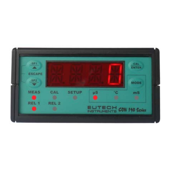
3 OVERVIEW 3.1 Front Panel The front panel consists of a 4-digit LED display, 8 LED annunciators and 4 keys. Annunciators 1. REL 1 Displayed when Relay 1 is activated 2. REL 2 Displayed when Relay 2 is activated 3. MEAS Displayed in measurement mode 4. -
Page 7: Back Panel
3.2 Back Panel The back panel consists of three different connectors that can be used with removable terminal blocks (included): Caution RELAY1 RELAY2 PT100 1. VAC live wire 2. VAC neutral wire 3. unused 4. unused 5. Relay 2 deactivated position (normally closed) 6. -
Page 8: Wiring
3.3 Wiring Caution: Ensure electrical mains are disconnected before proceeding. 1. Connect the power supply to the three-pin terminal block • VAC live wire = 1 • VAC neutral wire = 2 • VAC protective ground wire = 20 OR 21 α... -
Page 9: Ferrite Assembly
Wall panel Catch Catch Threaded rod Threaded rod SIDE VIEW approx. 100 TOP VIEW 3.5 Ferrite Assembly The power cable (L, N & E) needs to be connected to the instrument with two turns through the Split Ferrite which is supplied as an accessory with the instrument. It is strongly suggested that the Ferrite element supplied as a standard accessory be installed as described below. -
Page 10: Measurement Mode
4 MEASUREMENT MODE α lpha CON 190 controller is capable of taking conductivity measurement with Automatic (ATC) or Manual (MTC) Temperature Compensation. The measurements are displayed distinguishingly by the annunciators on the front panel. 4.1 Measurement mode display Press the MODE key to toggle between Conductivity and Temperature measurement mode. -
Page 11: Set Points Adjustments
4.2 Set Points Adjustments You can make quick set points adjustments with the direct access of the Set Points adjustment modes (SP1 and/or SP2). By just pressing the SP1/▲ or SP2/▼key, you can enter the Set Point adjustment mode and set a new Conductivity value that will cause your controller to activate. -
Page 12: Password
The Setup mode is to be accessed by entering a password code. The direct accessed Set Point adjustment mode (SP1 and SP2) and the Calibration mode can also be accessed through this password code procedure. The alpha CON 190 controller features two separate passwords: • Conductivity and Temperature calibration mode password = 011 •... - Page 13 P . 000 P . 000 P .0 1 0 P .020 P . 0 11 P . 022 P . 0 11 P . 022...
-
Page 14: Conductivity Calibration
6 CONDUCTIVITY CALIBRATION IMPORTANT: When Calibration mode is entered, controller automatically goes into a “HOLD” mode where the 4-20 mA output freezes and relays are de-activated (if it was in an activated condition). Upon return to measurement mode, both 4-20mA output and relay activities resume, depending on settings. - Page 15 If calibration is successful, Controller displays DONE, blinking. Press ENTER to revert to Conductivity measurement mode (Relays and 4-20 mA output resume previous settings). NOTE: To clear the ERR1 display and return to calibration mode, press ▲/ ▼ keys together. 50 9 50 0 ENTER...
-
Page 16: Temperature Calibration
7 TEMPERATURE CALIBRATION IMPORTANT: When Calibration mode is entered, controller automatically goes into a “HOLD” mode where the 4-20 mA output freezes and relays are de-activated (if it was in an activated condition). Upon return to measurement mode, both 4-20mA output and relay activities resume, depending on settings. -
Page 17: Setup Mode
8 SETUP MODE 8.1 General Information IMPORTANT: When Setup mode is entered, controller automatically goes into a “HOLD” mode where the 4-20 mA output freezes and relays are de-activated (if it was in an activated condition). Upon return to measurement mode, both 4-20mA output and relay activities resume, depending on settings. -
Page 18: Setup Mode Overview
8.2 Setup mode overview P1.0: Set Point 1 P1.1: select relay 1 set point value P1.2: select relay 1 as low or high set point P1.3: set relay 1 hysteresis value P2.0: Set Point 2 P2.1: select relay 2 set point value P2.2: select relay 2 as low or high set point P2.3: set relay 2 hysteresis value P3.0: Range... -
Page 19: Set Point 1 - P1.0
8.3 Set Point 1 – P1.0 Setup program P1.0 allows you to set parameters for relay 1. P1.1: select relay 1 set point value P1.2: select relay 1 as low or high set point P1.3: set relay 1 hysteresis value (dead band) P 1 .0 P 1 .1 P 1 .2... - Page 20 P1.3: Set Hysteresis value Hysteresis prevents rapid contact switching if measured value is fluctuating near the set point. Once activated, relay will not de-activate until measured value reaches set point plus hysteresis value. Example: Low set point is 200.0 µS/cm and hysteresis 100.0 µS/cm, relay will activate when value drops below 200.0 µS/cm, but will not de-activate till measured Conductivity value rises above 300.0 µS/cm.
-
Page 21: Set Point 2 - P2.0
8.4 Set Point 2 – P2.0 Setup program P2.0 allows you to set parameters for relay 2. P2.1: select relay 2 set point value P2.2: select relay 2 as low or high set point P2.3: set relay 2 hysteresis value (dead band) P 2 .0 P 2 .1 P 2 .2... - Page 22 P2.3: Set Hysteresis value Hysteresis prevents rapid contact switching if measured value is fluctuating near the set point. Once activated, relay will not de-activate until measured value reaches set point plus hysteresis value. Example: High set point is 1800.0 µS/cm and hysteresis 100.0 µS/cm, relay will activate when value rises above 1800.0 µS/cm, but will not de-activate till measured Conductivity value drops below 1700.0 µS/cm.
-
Page 23: Measurement Range Selection - P3.0
8.5 Measurement Range Selection – P3.0 Setup program P3.0 is for selecting the range of measurement. P3.1: select measurement range and corresponding cell constant P 3 . 0 P 3 . 1 R N GE 2000 K 10 . Press ▲and ▼keys together (ESCAPE) at anytime, to leave the Setup mode and return to Measurement mode. -
Page 24: Configure Temperature Settings - P4.0
8.6 Configure Temperature Settings – P4.0 Setup program P4.0 is for selecting ATC or MTC, set temperature coefficient values, and select normalization temperature P4.1: ATC or MTC mode (default : ATC mode) P4.2: set temperature coefficient (default : 2.10 %) P4.3: set Normalization temperature (default : 25.0 P 4 .1 P 4 .2... -
Page 25: Viewing Conductivity Calibration Data - P5.0
8.7 Viewing Conductivity Calibration Data – P5.0 Program 5 is a “view only” option, which displays the value at which calibration was performed. P5.1: view Calibrated conductivity value (if no calibration performed for this range, controller displays ‘- - - - ‘). These parameters will change each time you recalibrate the controller. -
Page 26: Viewing Conductivity/ Temperature Electrode Data - P6.0
8.8 Viewing Conductivity/ Temperature Electrode Data – P6.0 Program 6 has two “view only” options that let you check the electrode parameters for diagnostic purposes. P6.1: view revised cell constant value of electrode P6.2: view temperature probe offset (ATC on only) These parameters will change each time you recalibrate the controller. -
Page 27: Controller Reset - P7.0
8.9 Controller Reset – P7.0 Program 7 gives an option to reset the controller to factory default values. • Conductivity range remains unchanged based on last selected range • All calibration data and conductivity calibration factor are reset • SP 1 is reset to 10 % of full scale •... -
Page 28: Relays
9 RELAYS α lpha CON 190 features two SPDT non-powered relays; rated for 6A at 110 VAC, 250 VAC maximum. When your process exceeds the set parameters of a relay set point, the REL 1 or REL 2 indicator will light up. To set parameters for relay 1 and relay 2, see Setup programs P1.0 and P2.0. -
Page 29: Specifications
11 SPECIFICATIONS Conductivity Range Resolution Cell Constant 0.00 – 20.00 µS/cm 0.01 µS/cm 0.0 – 200.0 µS/cm 0.1 µS/cm 0.0 – 200.0 µS/cm 0.1 µS/cm 0 – 2000 µS/cm 1 µS/cm 0.00 – 10.00 mS/cm 0.01 mS/cm 0.00 – 20.00 mS/cm 0.01 mS/cm 0.0 –... -
Page 30: Accessories
12 ACCESSORIES Product Description Code no. Conductivity cell, Epoxy body, Graphite sensor, w/3-wire ECCONSEN89X Pt100, k = 0.1 Conductivity cell, Epoxy body, Graphite sensor, w/3-wire ECCONSEN88X Pt100, k = 1.0 EC-CS10-0-1S Conductivity 2 Cell type probe, 0.1 - 200µS; Cell constant, K=0.1 with integrated Pt 100, Material SS316 and 25ft cable (open-ended) Conductivity 2 Cell type probe, up to 200 mS;... - Page 31 Appendix 1: Simple Explanation on the Function of Hysteresis The controller relay activates when the set- SP1 Set to LO SP2 Set to HI RELAY ON point is reached. In the reverse direction, it does not de-activate when the value reaches the set-point.
- Page 32 Appendix 3: External Relays α The relays on the lpha CON 190 series controller are rated for 6 amps at 110 VAC and can be wired directly to your final control element (provided its power requirements does not exceed this). However, to preserve the life of your controller, or if higher power is needed, it is recommended that you use the controller relay to drive an external relay.
-
Page 33: General Information
13 GENERAL INFORMATION Warranty Eutech Instruments warrants this product to be free from significant deviations in material and workmanship for a period of one year from the date of purchase. If repair is necessary and has not been the result of abuse or misuse within the warranty period, please return by freight pre-paid and amendment will be made without any charge. - Page 34 For more information on Eutech Instruments products, contact your nearest Eutech Instruments distributor or visit our website listed below: Manufactured by: Distributed by: Eutech Instruments Pte Ltd. Blk 55, Ayer Rajah Crescent, #04-16/24 Singapore 139949 Tel: (65) 6778 6876 Fax: (65) 6773 0863 E-mail: marketing@eutechinst.com...
Need help?
Do you have a question about the alpha CON 190 and is the answer not in the manual?
Questions and answers