Table of Contents
Advertisement
Quick Links
Advertisement
Table of Contents

Summary of Contents for Apoolco ASPT-20
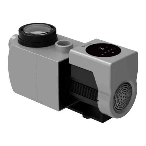
- Page 1 INVERTER POOL PUMP INSTALLATION AND OPERATION MANUAL...
-
Page 2: Table Of Contents
Content IMPORTANT SAFETY INSTRUCTIONS ................1 2 TECHNISCHE DATEN ......................2 3 OVERALL DIMENSIONS ......................2 4 INSTALLATION ........................3 5 SETTING AND OPERATION ..................... 5 6 WIFI-OPERATION ....................... 10 7 EXTERNAL CONTROL ......................17 8 PROTECTION AND FAILURE ....................19 9 MAINTENANCE ........................ -
Page 3: Important Safety Instructions
MPORTANT AFETY NSTRUCTIONS This guide provides installation and operation instructions for this pump. If you have any other questions about this equipment, please consult your supplier. When installing and using this electrical equipment, basic safety precautions should always be followed, including the following: •... -
Page 4: Technische Daten
ECHNISCHE ATEN Model Advised pool Voltzage Qmax Hmax Circulation (m³/h) volumen (kW) (V/Hz) (m³/h) at 8m at 4m (m³/h) ASPT-20 30-50 0.75 23.7 11.3 17.4 11.6 220-240/ ASPT-24 40-70 1.05 26.3 13.9 23.1 19.5 50/60 ASPT-30 60-90 28.7 16.7 27.5 25.1... -
Page 5: Installation
NSTALLATION Pumpenstandort 1) Install the pump as close to the pool as possible, to reduce friction loss and improve efficiency, use short, direct suction, and return piping. 2) To avoid direct sunshine, heat, or rain, it is recommended to place the pump indoors or in the shade. - Page 6 Valves and Fittings 1) Elbows should not be closer than 350mm to the inlet. Do not install 90° elbows directly onto the pump inlet/outlet. Joints must be tight. 2) Flooded suction systems should have gate valves installed on suction and return line for maintenance.
-
Page 7: Setting And Operation
ETTING AND PERATION Display on control panel ① Power consumption ② Running capacity / Flow rate ③ WIFI indicator ④ Unit of flow ⑤ Timer period ⑥ Timer 1/2/3/4 Backwash/unlock Up/down: to change the value ... - Page 8 (22 m³ /h), and the flow display on the controller will turn back to 22 m³/h after 3 seconds. The default adjustable flow range is as below: Model Default adjustable flow rate range ASPT-20 5-20 m³/h ASPT-24 5-25 m³/h ASPT-24 5-30 m³/h...
- Page 9 Backwash User can start the backwash or fast re-circulation in any running state by pressing Default Setting range Press to adjust from 0 to 25 minutes with 30 Time 3 minutes seconds for each step Running 100% 80-100%, enter the parameter setting (see 5.8) Capacity If backwash is completed or disabled press and hold for 3 seconds, the pump will return to...
- Page 10 Note: The pump will define the adjustable flow range after the first self-priming. The pipeline pressure will be recorded by the system after the pump was running at the set flow/capacity for 3 minutes without disruption. If it is detected that the pipeline pressure changes beyond a certain range during operation, the icon of % or m³/h (or other flow unit) symbol will flash for 5 minutes.
- Page 11 Parameter Setting Restore factory setting In off mode: hold both for 3 seconds. Check the software In off mode: hold both for 3 seconds. version Manual priming In on mode: hold both for 3 seconds. Enter parameter setting In off mode: hold both for 3 seconds;...
-
Page 12: Wifi-Operation
6 WIFI-O PERATION InverFlow Download Account registration Register by e-mail (a) or third-party application (b) InverFlow App Android a) E-Mail registration... - Page 13 b) Third-party application registration Create home Please set home name and choose the location of the device (it is recommended to set the location so the weather can be shown in the App for your convenience).
- Page 14 App Pairing Please make sure your pump is switched on before you start. Option 1 (recomended): Wifi and Bluetooth (Network requirement: 2.4GHz; 2.4Ghz and 5GHz in one SSID; no separate 5GHz network) 1) Please confirm that your phone is connected to Wifi and your Bluetooth is activated. 2) Press for 3 seconds until you hear “Beep”to unlock the screen.
- Page 15 Option 2: Wifi (Network requirement: 2.4GHz only) 1) Please confirm that your phone is connected to the Wifi. 2) Press for 3 seconds until you hear “Beep”to unlock the screen. Press for 5 seconds until you hear “Beep”, then release the button. The symbol will flash.
- Page 16 Operation 1) Using Auto Inverter mode: Change flow rate units Error code list Real-time power Real-time running capacity consumption Turn the control dial to set the flow rate Auto Inverter mode Data Timer On/Off Backwash 2) Using Manual Inverter mode: Real-time power Real-time running capacity consumption...
- Page 17 Sharing devices with your family members If your family members also want to control the device after pairing, please let them register in the app“InverFlow”first, then the administrator can operate as below:...
- Page 18 Feedback If any problems should occur during operation, you are very welcome to send your feedback. Notice: 1) The weather forecast is just for reference. 2) The power consumption data is for reference only, as it may be affected by network problems and imprecision of the calculation.
-
Page 19: External Control
XTERNAL ONTROL An external control can be enabled via the following contacts. If more than one external control is enabled, the priority is as follows: Digital input > Analog input > RS485 > Panel control Connector for configurable user inputs, including digital input, analog input and RS485 Relay output AC Power input... - Page 20 Pin-Configuration Name Color Description PIN 1 Digital Input 4 PIN 2 Black Digital Input 3 PIN 3 White Digital Input 2 PIN 4 Grey Digital Input 1 PIN 5 Yellow Digital Ground PIN 6 Green RS485 A PIN 7 Brown RS485 B PIN 8 Blue...
-
Page 21: Protection And Failure
ROTECTION AND AILURE High Temperature Warning and Speed Reduction In “Auto-Inverter/Manual-Inverter Mode” and “Timer mode” (except backwash/self- priming), when the module temperature reaches the high temperature warning trigger threshold (81℃), it enters the high temperature warning state; when the temperature drops to the high temperature warning release threshold (78℃), the high temperature warning state is ended. - Page 22 Trouble shootiung Problem causes and solution Pump does not start Power Supply fault, disconnected or defective wiring. Fuses blown or thermal overload open. Check the rotation of the motor shaft for obstacles and mobility. Caused by long immobility. Unplug the power supply and manually rotate motor rear shaft a few times with a screwdriver.
-
Page 23: Maintenance
AINTENANCE Empty the strainer basket frequently. The basket should be inspected through the transparent lid and emptied if there is an evident stack of rubbish inside. The following instructions should be followed: 1) Disconnect the power supply. 2) Unscrew the strainer basket lid anti-clockwise and remove. 3) Lift up the strainer basket.
Need help?
Do you have a question about the ASPT-20 and is the answer not in the manual?
Questions and answers