Table of Contents
Advertisement
Quick Links
Advertisement
Table of Contents

Summary of Contents for ProKeys PoKeys57CNCpro4x25
- Page 1 PoKeys57CNCpro4x25 User’s manual Version: v1.00...
- Page 2 16. The licensee agrees to allow access to this software only to persons who have been informed of and agree to abide by these conditions. 17. Trademarks: Windows is a registered trademark of Microsoft Corporation. PoKeys, PoKeys55, PoKeys56U, PoKeys56E, PoKeys57U, PoScope, PoLabs and others are internationally registered trademarks. PoKeys57E, PoKeys57CNC, PoKeys57CNCpro4x25, PoKeys57CNCdb25, www.poscope.com...
-
Page 3: Table Of Contents
PoKeys57CNCpro4x25 user manual v1.00 Contents Introduction ............................. 6 Features ............................7 Device hardware description - PoKeys57CNCpro4x25 v1.00 ............8 PoKeys57CNCpro4x25 connector pinout ..................9 4.1. Pin types ..........................9 4.2. Power supply ........................... 9 4.3. Relay connector ........................10 4.4. - Page 4 Using USB ..........................20 7.2. Using Ethernet - direct connection between PoKeys57CNCpro4x25 and computer .... 20 7.3. Using Ethernet - PoKeys57CNCpro4x25 connected to a network with DHCP server ... 21 7.1. Using USB and Ethernet ......................21 PoKeys configuration options ......................22 8.1.
- Page 5 PoKeys57CNCpro4x25 user manual v1.00 8.11. Saving current configuration to file ................... 43 8.12. PoIL core functionality ....................... 43 Device recovery mode ........................44 Frequently asked questions ...................... 45 Errata information ........................46 Change log ..........................47 Grant of license ......................... 48...
-
Page 6: Introduction
CAN bus interface. PoKeys57CNCpro4x25 features both USB and Ethernet connectivity, giving user an option to select the preferred connection for the application. The device is highly adjustable and as such requires no complex knowledge on device programming. -
Page 7: Features
PoKeys57CNCpro4x25 user manual v1.00 2. Features 4 dedicated digital inputs (24 V compatible) for connecting home/limit switches, 1 dedicated digital input (24 V compatible) for probe input, 1 analog input (12-bit, 0-10 V range) with analog low-pass filter with 1.9 kHz cut-off frequency,... -
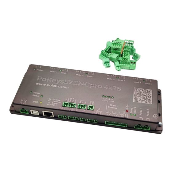
Page 8: Device Hardware Description - Pokeys57Cncpro4X25 V1.00
PoKeys57CNCpro4x25 user manual v1.00 3. Device hardware description - PoKeys57CNCpro4x25 v1.00 www.poscope.com... -
Page 9: Pokeys57Cncpro4X25 Connector Pinout
The power supply should be capable of providing at least 150 W (e.g. 24 V 6 A power supply). Power supply for PoKeys57CNCpro4x25 is powering the device as well as the motors with motor drivers. It is designed for 24 V power supply which is then distributed to motor drivers and limit switches. -
Page 10: Relay Connector
PoKeys57CNCpro4x25 user manual v1.00 4.3. Relay connector Pin Type Function Relay 2 NO Relay 2 common Relay 1 NO Relay 1 common Relay connectors are normally open (NO) configuration and enable you to switch higher loads on/off. 4.4. Galvanically isolated I/Os This connector contains special I/O signals that are galvanically isolated from the rest of the board. -
Page 11: Can Connector
CAN high signal Ground +5 V power supply to CAN bus The CAN bus on PoKeys57CNCpro4x25 is intended for all the peripheral devices that we already offer and that we will add in the future. There are two connectors, one with additional power supply of 5 V. -
Page 12: Analog Input
PoKeys57CNCpro4x25 user manual v1.00 4.7. Analog input Pin Type Label Function Ground PWR24 24V Power supply for analog sensor AI10F Analog input 10 V range Analog input with 0-10 V range as industry standard. Intended for connecting peripheral sensors and devices with analog voltage output. -
Page 13: Axis Limit Switches Connector 1-4
PoKeys57CNCpro4x25 user manual v1.00 4.10. Axis limit switches connector 1-4 Pin Type Label Function Ground DINPN Signal input from limit switch NPN type Axis Limit pin (PoKeys pin input) Pin 26 Pin 25 Pin 24 Pin 23 PWR24 24 V limit switch power supply Dedicated limit+ switch connectors are located next to each motor output. -
Page 14: E-Stop Input
PoKeys57CNCpro4x25 user manual v1.00 4.12. E-stop input Pin Type Label Function Ground DINPN Signal input for E-stop NPN type E-stop connector is wired the same as limit switch and probe, but there is no power supply on the connector. The ordinary switch should be wired between signal and GND input. -
Page 15: Type Di33: 3,3 V Digital Input
PoKeys57CNCpro4x25 user manual v1.00 Type DI33: 3,3 V digital input Digital pin directly connected to MCU with series resistor. Symbol Parameter Unit maximum voltage applied to DI5 pin DI5,MAX applied voltage for LOW state DI5,LOW applied voltage for HIGH state... -
Page 16: Type Rel: Relay Output
PoKeys57CNCpro4x25 user manual v1.00 Type REL: relay output Symbol Parameter Unit maximum current switching at 28 VDC REL,28VDC maximum current switching at 125 VAC REL,125VAC maximum current switching at 240 VAC REL,240VAC maximum voltage of the load REL,MAX Type AI10F: 10 V analog input with 1,9 kHz low-pass filtering... -
Page 17: Type Ao10F: 10 V Analog Output With Low-Pass Filtering
PoKeys57CNCpro4x25 user manual v1.00 Type AO10F: 10 V analog output with low-pass filtering Symbol Parameter Unit analog output voltage Type DINPN: Digital input NPN Symbol Parameter Unit Input activation current Maximum sensor power supply current (combined on all limit and probe sensor power supply ports) Type AN33F: 3.3 V analog input with low-pass filter... -
Page 18: Status Leds
5. Requirements 22 V - 26 V power supply with 150 W or more, Ethernet or USB 2.0 connection between host computer and PoKeys57CNCpro4x25 device Included software requires Windows XP/Vista/7/8/8.1/10/11 with .NET framework 3.5 installed. -
Page 19: Technical Specifications
PoKeys57CNCpro4x25 user manual v1.00 6. Technical specifications 6.1. PoKeys57CNCpro4x25 dimensions Measurements are in mm. 6.2. Electrical and environment specifications Parameter Unit Power supply range Operating temperature °C Storage temperature °C Humidity 95 (non-condensing) % RH www.poscope.com... -
Page 20: Installation
Note: USB connection is not galvanically isolated 7.2. Using Ethernet - direct connection between PoKeys57CNCpro4x25 and computer Network firewalls must allow all traffic on TCP/UDP port 20055 between PoKeys57CNCpro4x25 device and PoKeys-related software running on a computer. Step 0 (prerequisite): install PoKeys setup package (version 4.7.9 or newer) -
Page 21: Using Ethernet - Pokeys57Cncpro4X25 Connected To A Network With Dhcp Server
7.1. Using USB and Ethernet PoKeys57CNCpro4x25 device can be connected to the computer by using both the USB and Ethernet connection. In this case, applications will detect two instances of PoKeys57CNCpro4x25 devices and USB connection will be selected by default by third-party applications. -
Page 22: Pokeys Configuration Options
Note: if PoPendant is connected to the PoKeys57CNCpro4x25 over CAN, PoKeys pins 3-6, 9-11 and 15- 16 will represent the state of the PoPendant signals (axis and step selection switches), as in PoKeys57CNC. -
Page 23: Encoders
– green for the activated (HIGH state) and white for the unactivated (LOW state). Not all squares that are rendered in this display represent an actual pin on the PoKeys57CNCpro4x25. To change the digital output state, first enable ‘Enable output control’ option, then either left or right click with mouse on the square representing the digital output to activate or deactivate this output. - Page 24 PoKeys57CNCpro4x25 user manual v1.00 Fast encoders are not intended to be used natively on PoKeys57CNCpro4x25 because of the lack of extenally available digital IO pins. Figure 3: Encoder settings in PoKeys application www.poscope.com...
- Page 25 Fast encoders are disabled so only ultra fast encoder is relevant. At the bottom of the window, there is a command button that can be used to reset the encoders’ values. Note: if PoPendant is connected to the PoKeys57CNCpro4x25 over CAN, encoder 1 will represent the encoder on the PoPendant itself.
-
Page 26: Pulse Engine
8.3. Pulse engine PoKeys57CNCpro4x25 is a hybrid device between a PoKeys57CNC device and a set of PoStep25-256 stepper motor drivers. As such, it contains an external pulse generator on-board, which is driving 4 stepper motor drivers by STEP/DIR signals with maximum pulse frequency of 125 kHz. -
Page 27: Pulse Engine Status/Control Dialog Parts
Enable backlash compensation: check this option to enable the backlash compensation in PoKeys device. 2. Pulse generator options: PoKeys57CNCpro4x25 contains an external pulse generator on- board, thus external pulse generator option with ‘Extended IO’ must be selected. 4 axes are enabled by default. -
Page 28: Axis Configuration Panel
PoKeys57CNCpro4x25 user manual v1.00 a. Relays 1 and 2 control the relays on board. b. Plasma controlls the plasma output for relay on PlasmaDiv c. OC-outputs control the galvanically isolated open-collector outputs Axis configuration panel This panel contains settings for each axis. -
Page 29: Homing Algorithm Configuration
PoKeys57CNCpro4x25 user manual v1.00 9. Motion parameters: use these fields in case that Internal motion controller is enabled to setup the maximum speed, acceleration and deceleration values. When the value is entered into the fields, confirm the value by pressing ‘Enter’ (‘Return’) key - the field will change color from red to white. -
Page 30: Common Homing Algorithm Configurations
PoKeys57CNCpro4x25 user manual v1.00 Figure 8: Built-in help Common homing algorithm configurations Although the homing algorithm is configurable, there are some standard configurations that fit most CNC machine configurations: 1. Standard homing configuration 2. Homing without reverse 3. Homing with encoder index - standard 4. -
Page 31: Limit And Home Switch Filters
42 is intended for plasma voltage input. There are two more analog channels on PoKeys57CNCpro4x25 for monitoring temperature and input supply voltage to the board. Analog inputs have a resolution of 12 bits and are sampled at a fixed rate of 10 kHz. -
Page 32: Pwm Outputs
Figure 9: Analog inputs and outputs dialog 8.5. PWM outputs PoKeys57CNCpro4x25 device supports PWM output function on pins 17 and 20. Pin 17 is wired to 0- 10 V output for spindle control – the output voltage is proportional to the duty cycle of the PWM output. -
Page 33: Failsafe Settings
PoKeys57CNCpro4x25 user manual v1.00 Figure 11: PWM outputs settings In this window, user can enter PWM period and set PWM duties for each channel. Channels can be independently enabled or disabled. After a change is made, user must click 'Set values' button or check 'Send to device on change' checkbox. - Page 34 PoKeys57CNCpro4x25 user manual v1.00 Figure 12: Failsafe settings dialog www.poscope.com...
-
Page 35: Peripheral Communication Protocols
8.7. Peripheral communication protocols CAN bus PoKeys57CNCpro4x25 also features CAN bus. CAN bus is a robust communication bus standard designed for use in automotive and industrial environments. CAN bus in PoKeys devices is used to support PoCAN communication protocol between PoKeys devices and peripherals. It is intended for devices such as PoRelay8 or kbd48CNC keyboard and others. -
Page 36: Communication Interval
PoKeys57CNCpro4x25 user manual v1.00 in BIOS not detecting the device and continuing the boot sequence. Adjust the value according to your system in this case. Communication interval By default, PoKeys USB devices use 1 millisecond communication interval for the communication interface. -
Page 37: Network Device Functionality
PoKeys57CNCpro4x25 user manual v1.00 8.9. Network device functionality PoKeys57CNC device can be connected to Ethernet 10/100 network with standard RJ-45 cable. By default, the device is set to use the DHCP functionality of the network router. User can later turn on or off the DHCP support. -
Page 38: Default Network Settings
PoKeys57CNCpro4x25 user manual v1.00 Default network settings DHCP: enabled Port: 20055 Security: Full access Connecting to device in other network When the device is not detected automatically (either there is a firewall blocking the UDP broadcast messages or the device is not in the same network as a computer), custom IP address of the device can be entered by clicking on the 'Network settings... -
Page 39: Security
PoKeys57CNCpro4x25 user manual v1.00 Security Due to exposed nature of a network device, an authentication mechanism was implemented in network PoKeys that allows three levels of access rights: Full access (default): the device is fully accessible from the network Read-only access: unauthorized users are allowed only to fetch a limited set of data from the device, while an authenticated users can acccess all functions of the device Full lock: unauthorised users can not neither read or write to the device. -
Page 40: Modbus
Modbus PoKeys57CNCpro4x25 device supports slave (server) operation of Modbus TCP communication protocol. Modbus TCP compatible devices on the network can read the values from the device and set the outputs. To elevate the security, user can define which peripherals are accessible via Modbus TCP. - Page 41 PoKeys57CNCpro4x25 user manual v1.00 202,203 PWM duty1 (MSB first) – pin 22 212,213 PWM duty6 (MSB first) – pin 17 300-304 PoExtBus 400-453 (400-499 on Sensors (32-bit values, LSB first) PoKeys57 series) Tick counter (lower 16-bit) 700-751 R[W] Digital encoder values (32-bit values,...
- Page 42 PoKeys57CNCpro4x25 user manual v1.00 Figure 17: Modbus configuration www.poscope.com...
-
Page 43: Changing User Id Number
PoKeys57CNC contains PoIL core that is fully compatible with other PoKeys devices. Read the separate PoIL core documentation for more information. Due to the omission of the 3V lithium backup battery, PoKeys57CNCpro4x25 does not support value retention in case of power failure. -
Page 44: Device Recovery Mode
1. Disconnect PoKeys57CNCpro4x25 device from USB and remove power supply. Unscrew and remove the aluminium cover of the device to access the PCB board and the jumper. 2. Locate the jumper between the USB and ETHERNET connector on the PoKeys57CNCpro4x25 device and short the pins as shown below: 3. -
Page 45: Frequently Asked Questions
Yes, both USB and Ethernet connections can be connected at the same time, but USB connection will have a priority over Ethernet. Windows can not find drivers for PoKeys57CNCpro4x25 device The drivers should automatically be installed by PoKeys setup package. If this is not the case and... -
Page 46: Errata Information
PoKeys57CNCpro4x25 user manual v1.00 Errata information www.poscope.com... -
Page 47: Change Log
PoKeys57CNCpro4x25 user manual v1.00 Change log V1.00 initial revision www.poscope.com... -
Page 48: Grant Of License
We provide upgrades, free of charge, from our web site at www.poscope.com. We reserve the right to charge for updates or replacements sent out on physical media. Trademarks Windows is a registered trademark of Microsoft Corporation. PoKeys, PoKeys55, PoKeys56U, PoKeys56E, PoKeys57E, PoKeys57U, PoKeys57CNC, PoKeys57CNCpro4x25, PoStep25, PoStep60, PoScope, PoLabs and others are internationally registered trademarks. support: www.poscope.com...
Need help?
Do you have a question about the PoKeys57CNCpro4x25 and is the answer not in the manual?
Questions and answers