Table of Contents
Advertisement
Quick Links
Advertisement
Table of Contents

Related Manuals for iCoolsport Turbo 5 Series

Summary of Contents for iCoolsport Turbo 5 Series
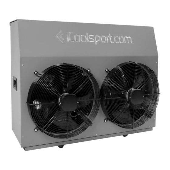
- Page 1 Turbo Series 5 User Manual...
-
Page 2: Table Of Contents
Contents 1. Safety Precautions............................3 2. Getting Started ..............................4 2.1 Basic Information ............................4 2.2 In the Box ..............................5 2.4 Installation ..............................5 Location ....................................... 5 Clearances ....................................6 Airflow ......................................7 Waterflow ....................................7 Condensation ....................................7 Connections .................................... -
Page 3: Safety Precautions
Instructions given within this manual must be followed. Failure to do so will result in warranty being voided. Do not perform any modifications of the unit without approval of iCoolSport. Never place anything within the minimum clearances that could restrict airflow. -
Page 4: Getting Started
2. Getting Started Welcome to your new iCoolSport Turbo. The Turbo unit is a high-power high-performance heat pump designed to chill or heat medium sized recovery pools. Before getting started, please inspect the package contains everything and that there is no transportation damage. -
Page 5: In The Box
2.2 In the Box Part Name Part Name Turbo Unit User Manual 40mm Barrel Union (Sometimes found Control Display already attached to the unit) DB9 Connector 8P Data Connector 20m Data Cable 2.4 Installation Location The Turbo unit must be installed in an open, well ventilated area. It is recommended that the unit is installed outside, however if it is installed indoor, it must meet the minimum floor area requirements and have adequate ventilation. -
Page 6: Clearances
Clearances The unit must be installed with the minimum clearance distances maintained. Failure to do so may result in degradation of performance or, in extreme cases, irreversible damage. Adequate spacing must also be maintained for future servicing and maintenance. -
Page 7: Airflow
Airflow The Turbo unit contains two 450mm fans that push through 4000cfm of air over the condensers of the unit. If the unit is installed in an enclosure area, the same amount of air must be circulated through the room to ensure that the unit can maintain full performance. -
Page 8: Plumbing
Plumbing The Turbo unit has two 40mm PVC barrel union connections. 40mm Pressure fittings are used and 40mm pressure pipe is required for all plumbing. If a fixed speed pump with a greater flowrate than the optimal values given is used, it is recommended that a bypass valve is installed to reduce the flowrate to the optimal. -
Page 9: Wiring
Wiring The Turbo unit has three basic connections that must be completed for the unit to correctly operate. The connections are main power supply, pump, and data. All connections must be completed within local regulations and standards by a licensed electrician. Pump power output has a max current of 10A continuous. - Page 10 7. Reconnect the button harness and rescue the side panel. Ensure all hex screws are reinstalled and do not overtighten.
-
Page 11: Display
Display Mounting The Display is not waterproof. It must be mounted away from any direct water splashing and rain. It is ideal to mount the screen in an area or room away from water where the humidity is also low. The display has two options for mounting. -
Page 12: Installation Checklist
Installation Checklist Use the checklist below to ensure everything has been completed before turning the unit on for the first time. ☐ Unit has been installed securely. ☐ Area has adequate ventilation. ☐ Unit has protection from direct sunlight and rain. ☐... -
Page 13: First Start
2.4 First Start Before starting the unit for the first time, ensure that the installation checklist has been completed. Then power the unit on and ensure that the unit’s internal lights turn on (located behind the side panel on the right side of the turbo unit). -
Page 14: Technical Data
3. Technical Data 3.1 Specifications Model Specification Unit Cool Voltage 220-240 220-240 220-240 Frequency 50/60 50/60 50/60 Power 3.77 Current 15.72 Airflow 4000 @ 1m Noise @ 3M Dimensions (L x W x H) 1070 x 510 x 835 Water connection type 40 (Pressure) Weight Temperature... -
Page 15: Dimensions
3.2 Dimensions... -
Page 16: Operation
5. Operation 5.1 Controller Functions Main Menu Icon Function Description Menu Button to open the menu tab to navigate to other pages. Start/Stop Button to start or stop the chilling or heating of the unit, to the current set temperature. Current set temperature Displays the current set target temperature. - Page 17 “Current Set Temperature” will now display the new desired target temperature. Press to start the system. The system will now attempt to start and will cool/heat to the set target temp. Changing the Target Temperature while System in Operation Increase or decrease the set temperature to the desired target temperature by pressing the buttons.
- Page 18 Settings Menu Icon Function Description Toggle Manual Pump Toggle pump on and off when unit is in the off state. The settings menu contains user settings to configure the Turbo unit. The manual pump setting can be used to prime the system. This option will turn on the pump while the system is in the off state and will continue to run until it is turned off again or the system is started from the start button.
- Page 19 The pin can be removed using the same pin code. If the pin is forgotten, please contact iCoolSport support on how to remove the pin. When setting a pin, a menu will open and will request the pin to be entered. Enter 4 digits to set the pin.
- Page 20 To remove the current set pin, simply press “Remove Pin”. A menu will appear to enter the current set pin. Enter the correct set pin and a dialog will prompt you to confirm this action. If the current set pin is forgotten, please contact iCoolSport Support on how to remove the pin. Function...
- Page 21 Device Information Menu Function Description Device ID Device ID of the unit. Model Model of the unit. Unit Unit. Version Software version of the display. The device information menu is useful for finding information about your Turbo unit. Disconnected Menu The disconnected menu will appear when the display is unable to make a connection to the Turbo unit.
-
Page 22: Unit
All Turbo units should be wired to a dedicated RCBO for protection. However, each unit does also include a secondary safety switch to protect it from over current and earth faults. If a fault occurs and this switch trips, please consult a refrigeration technician or iCoolSport support to resolve the issue before turning the safety switch back on. -
Page 23: Maintenance
6. Maintenance It is recommended that the unit is check yearly to ensure that it is operating at full performance. In installations close to the ocean or corrosive environments, this should be done more frequently at half yearly, minimum. Water quality management is subject to use load and the amount of water being used. It is recommended to contact your local pool shop for advice on how to treat the water as this will need to be done a regular basis. -
Page 24: Condensers And Cabinet
Condensers and Cabinet Cleaning the cabinet and condensers is vital for continual performance. If too much dirt and debris become stuck on the condensers, it is likely to lead to reduced airflow. The unit must be opened in order to gain access to both sides of the condensers. This also allows a perfect time to remove all loose debris inside the cabinet. -
Page 25: Display
6.2 Display Screen The screen should only be cleaned with distilled water. Do not use soaps or solvents as this may damage the coating on the display. 1. Use a cloth to wipe the display and remove any dust and debris. 2. -
Page 26: Troubleshooting
7. Troubleshooting Problem Reason Solution...
Need help?
Do you have a question about the Turbo 5 Series and is the answer not in the manual?
Questions and answers