Table of Contents
Advertisement
Quick Links
DTAC-102
INSTALLATION, USER AND
REFERENCE MANUAL
Thank you for purchasing the DTAC-102 solar pool heating controller, the most advanced on the
world market. DTAC-102 offers simple and intuitive user control for a solar pool heating system, ease
of configuration and a mobile App.
The App can remotely control, monitor and report the status and performance of your solar pool
heating system.
The DTAC system is backwards compatible with ASCON sensors, and DONTEK "Plus" sensors.
WARNING:
The DTAC product line is rated to supply a maximum combined power of 2.3kW under
Approval Certificate NSW29186. If the product is connected to equipment with a load greater
than 2.3kW then the DTAC may be damaged. The DTAC product must NOT be installed where
sustained overload can occur and it is not warranted under such usage. For a load greater
than 2.3kW then an AMATEK PS001A power separator must be used, which can take an
additional 2.4kW load, or 4.7kW in total. See Section 9 below for a system load calculator.
It is recommended to install the product under cover, not in direct sunlight, and in accordance
with AS/NZS 3000 and AS/NZS 3136.
UNIT UNIQUE ID (UUID)
Please retain this page for future reference
Advertisement
Table of Contents

Summary of Contents for Dtac DTAC-102
- Page 1 REFERENCE MANUAL Thank you for purchasing the DTAC-102 solar pool heating controller, the most advanced on the world market. DTAC-102 offers simple and intuitive user control for a solar pool heating system, ease of configuration and a mobile App. The App can remotely control, monitor and report the status and performance of your solar pool heating system.
-
Page 2: Table Of Contents
3.3.4 UUID Link Activation ....................... 8 3.3.5 Re-Activate ........................8 3.3.6 Delete Account ....................... 8 Control ........................... 8 Pump Timer and DTAC Time Settings ................... 9 3.5.1 Pump Timer ........................9 3.5.2 Update/Get DTAC Time ....................9 Statistics..........................9 3.6.1 Temperature Log ...................... - Page 3 Solar Gain ........................16 4.3.13 Freeze Control ......................17 4.3.14 FreezeThreshold ......................17 DTAC-102 Backwash procedure ....................17 UNIT SPECIFICATIONS ......................18 Approvals and Ratings ......................18 Sensor Compatibility List ..................... 18 Power Relay Ratings ......................18 Valve and Heater Relays ..................... 18 Valve actuator Port ......................
-
Page 4: Operation Summary
1 OPERATION SUMMARY The DTAC-102 is designed as a dual GPO, solar pool heating controller that can operate in standalone, single and dual pump retrofit modes, and with a sophisticated IoT capability integrated into current technology mobile devices. Control panel... -
Page 5: Installation
Mounting Mount the DTAC on a flat section of a wall using the mounting plate. The mount plate is secured by four screws at the rear of the housing which may be adjusted as necessary to allow the mounting plate freedom to slide. -
Page 6: Stand Alone Installation
Then insert the Phoenix plugs to the correct Phoenix socket as marked below, while leaving enough cable to do so. Finally slide the seal down the wires, press onto the terminal flange and push home until it is firmly in place. You may need to pull the wires gently through the holes to contain them. -
Page 7: Heater Interlock Connection
2.2.5 Heater Interlock Connection The DTAC-102H model can control an external heater with a dry contact closure. Use the same procedure as in Section 2.2.1 to connect the external heater's interlock cable to the interlock connector of the DTAC. 2.2.6 Phoenix Connector Pinout The Phoenix connector pinout is detailed in the schematic. -
Page 8: Mobile Device App
3 MOBILE DEVICE APP A mobile App is available for the DTAC on Android (version 7 and above) devices and iOS (version 15.5 and above) devices. The App provides a sophisticated yet simple and intuitive remote interface to user control, monitoring, status and performance reporting, configuration and diagnostics of your solar pool heating system. -
Page 9: User Sign In
- Enables activation and linking to a mobile device with the DTAC App Activation After Signing In for the first time you need to activate your DTAC unit which will then allow it to be remotely controlled by your mobile device. You must first complete the account creation, verification and "Sign In"... -
Page 10: Link Accounts
"CONNECT". Upon successful activation the "UNIT IS ACTIVATED" status message is displayed on the screen. Ensure you accept and enable Bluetooth and location permissions if requested. Once unit activation is completed the DTAC control menu is also available via a web interface (https://www.amatek.com/dtac). 3.3.2 Link Accounts Once a DTAC unit is activated and linked to the first user account then another user account can be linked to it. -
Page 11: Uuid Link Activation
To activate using a UUID, enter the UUID of the unit and click on the "Request Code" button. You must be close by the DTAC to read the 6 digit activation code displayed on its front panel. Enter the activation code and click "Submit Code". -
Page 12: Pump Timer And Dtac Time Settings
To update the DTAC time and timezone to Internet time and timezone, click the "Update Time" button. To update the Time Zone of the DTAC based on the source of cloud server of the App, click the drop down menu of the country/city, then click the "Set Timezone"... -
Page 13: Temperature Log
3.6.1 Temperature Log The TEMPERATURE LOG shows a time graph of the roof, set point, pool, and pipe where the pool sensor is located. The data-sets can be interactively removed or added by clicking on the data set's legend, for example clicking on the word "Roof"... -
Page 14: Plumbing Configuration
10 seconds and 600 seconds, done by dragging on or clicking its scroll bar. 3.7.3 Sensor Configuration and Position DTAC is the default, however click either "DTAC", "DONTEK" or "ASCON" to change the sensor type. The Roof Sensor Position setting can be configured by clicking "ROOF"... -
Page 15: Front Panel Operation
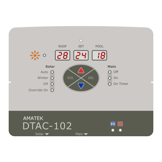
4 FRONT PANEL OPERATION The DTAC products can be operated from both the front panel and from a mobile App. The three LED displays show the ROOF, SET and POOL temperatures. SET displays the desired temperature when heating. There are four "buttons" on the front panel, UP, DOWN, SOL and SEL. In normal use the SEL button controls the main pump and mode, and the SOL button controls the solar pump and mode. -
Page 16: Set Time
While DTAC is setting up connection with the Cloud "Co nn" with dots animation will then be displayed Use the mobile App to enter the Wi-Fi passcode and wait for a few seconds If the Cloud is successfully connected, the display will show "5U CC E5"... -
Page 17: Time Window 1
1 for a Dontek analogue sensor 2 for an Ascon sensor 3 for a DTAC wireless sensor (Reserved for a future release so do not select) Pool and roof sensor types can not be individually selected, but are selected in pairs ... -
Page 18: Roof Sensor Position
4.3.7 Roof Sensor Position The roof sensor may be configured in one of two modes, with the DTAC start up default being Roof Up / Down (ud on the display) Roof (rooF on the display) When in Up / Down mode there is a pump priming period applied When in roof mode, no priming period is applied for sensing roof temperatures ... -
Page 19: Enable / Disable Heater
4.3.10 Enable / Disable Heater When "HE At Er" is displayed, press SEL to enter the menu The default heater state is "Off" Press UP / DOWN to change the heater state to "On" the text, "On" will start blinking if selected ... -
Page 20: Freeze Control
Press SEL to save the freeze threshold and exit or press SOL to exit without saving 5 DTAC-102 Backwash procedure Note that backwashing the pool with a retrofit system requires the solar pump to be turned off during the backwash as the system does not know the position of the filter's multiport valve, and if the solar gain is sufficient, then the solar pump will run with no water input, or the valve will move to the heating position. -
Page 21: Unit Specifications
6 UNIT SPECIFICATIONS Approvals and Ratings Approval Certificate NSW29186 Input 230VAC, 50Hz, 10A, 2.3kW Max Total Output Load 9.9A 2.28kW Insulation Double insulated water circuit IP rating IP33 (Keep out of direct sun, rain and pool zone) Temperature 0C - 40C Altitude 3,000m Sensor Compatibility List... -
Page 22: Warranty And Liability
WARRANTY AND LIABILITY Warranty on Hardware Subject to the following clause (1) SUPPLIER warrants that the goods delivered by SUPPLIER shall be free from defects in material and workmanship. SUPPLIER shall be released from obligations in the event that the goods are subject to misuse, neglect, accident, improper installation or any unusual or unrecommended physical, environmental or electrical stress (including improper voltage or power surge) by BUYER or if repairs or modifications are made by persons other than SUPPLIER's own or authorised service personnel (unless such... -
Page 23: Dtac Model Cross Reference
8 DTAC MODEL CROSS REFERENCE Feature Model Solar Main Wireless Valve Heater Chlorinator Pump Pump Remote Energy Monitor Relay Relay Input Relay Relay Support DTAC-101 DTAC-101S DTAC-102 ... -
Page 24: System Load Calculator
9 SYSTEM LOAD CALCULATOR Use this calculator to record the system power. If the total power is greater than 2300W, then an AMATEK PS001A power separator MUST be used. Failure to do so shall void the DTAC warranty. ACCEPTABLE SYSTEM LOAD EXAMPLE...
Need help?
Do you have a question about the DTAC-102 and is the answer not in the manual?
Questions and answers