
Subscribe to Our Youtube Channel
Summary of Contents for Slamtec LPX-E3P
- Page 1 LPX-E3P Industrial 2D Lidar Field Monitor Instruction Manual Model:LPX-E3P1 0.225°@20Hz for 64 zones SLAMTEC Inc.
-
Page 2: Table Of Contents
2.1 LPX-E3P System Composition ......2.2 LPX-E3P Working Schematic ...... - Page 3 8.1 Sensor label ........15 9.1 Indicator LEDs ........16 10.1 Reserve front space requirements .
-
Page 4: Features
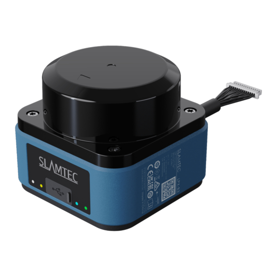
Introduction LPX-E3P is the next generation 2D Lidar Field Monitor developed by SLAMTEC with 64 con- figurable Field Sets, and 3 Field monitored simultaneously in each Field Set. By using wireless energy and data transmission technology, it beats the lifetime and reliability of traditional lidar. -
Page 5: System Composition
Class 1 human eye safety level. System Composition LPX-E3P consists of a range scanner core and the mechanical powering part, which makes the core rotate at a high speed. When it functions normally, the scanner core will rotate and scan clockwise. -
Page 6: Mechanism
The returning signal is then sampled by the laser acquisition system in LPX-E3P, and processor embedded in LPX- E3P starts processing the sample data and use internal Field Monitor App to detect the status for all selected fields in real-time. -
Page 7: Output Data
Through 6 input interfaces, 64 field sets can be selected, and 3 fields monitored at the same time can be switched. All zone groups need to be configured in SLAMTEC LPX SCAN DESIGNER software. In addition to the 3 output channels corresponding to the three fields monitored simultaneously, the sensor also provides a sensor working status output channel through which the working status of the sensor can be monitored. - Page 8 • Area intrusion monitoring • Channel passage monitoring This sensor is NOT suitable for the following fields: • Any fields a safety field scanner is required LIDAR SENSORS | SLAMTEC May 13, 2024 | Product datasheet Subject to change without notice...
-
Page 9: Safety And Scope
The modulated laser can effectively avoid interference from ambient light and sunlight during the ranging and scanning process, which makes the LPX-E3P work excellently in all kinds of indoor environments and outdoor environments without direct sunlight. This sensor is not a safety field scanner, do not use this sensor in unsuitable occasion. Please follow this document and use this sensor in applicable scenarios to avoid personal safety and property damage. -
Page 10: Detailed Technical Data
Integrated application Field Monitoring with flexible fields Number of field sets 64 Field Sets (3 Fields in each Field Set) Simultaneous evaluation cases 1 (3 fields) LIDAR SENSORS | SLAMTEC May 13, 2024 | Product datasheet Subject to change without notice... - Page 11 The sensor does not constitute a safety component as defined by relevant legislation on machine safety IEC 60068-2-6:2007. IEC 60068-2-64:2008. IEC 60068-2-27:2008. IEC 60068-2-14:2009. EN 60068-2-14:2009. EN 60068-2-14:2009. LIDAR SENSORS | SLAMTEC May 13, 2024 | Product datasheet Subject to change without notice...
-
Page 12: Lpx-E3P1 Detailed Technical Data Chart
SLAMTEC Industrial Solution LPX-E3P1 Classifications TODO Table 4.1: LPX-E3P1 detailed technical data chart LIDAR SENSORS | SLAMTEC May 13, 2024 | Product datasheet Subject to change without notice... -
Page 13: Dimensional Drawing
SLAMTEC Industrial Solution LPX-E3P1 Dimensional drawing Figure 5.1: Dimensional drawing LIDAR SENSORS | SLAMTEC May 13, 2024 | Product datasheet Subject to change without notice... -
Page 14: Working Range Diagram
SLAMTEC Industrial Solution LPX-E3P1 Working range diagram Figure 6.1: Working range diagram LIDAR SENSORS | SLAMTEC May 13, 2024 | Product datasheet Subject to change without notice... -
Page 15: Pin Assignment
Port action if Field 2 detect an object BLUE OUTPUT OUT3 Port action if Field 3 detect an object GREEN STATUS Port action if sensor fails Table 7.1: PIN assignment chart LIDAR SENSORS | SLAMTEC May 13, 2024 | Product datasheet Subject to change without notice... -
Page 16: Identify Sensor Information
The label in the picture above is for reference only. For specific parameter information, please refer to the product manual and the data on the label on the right side of the actual product. LIDAR SENSORS | SLAMTEC May 13, 2024 | Product datasheet Subject to change without notice... -
Page 17: Identify Work Status
Object detected in Field 2 (OUT2) Green Object detected in Field 3 (OUT3) Yellow Alignment mode Yellow Flashing Identificating device Table 9.1: Indicator light status vs working status LIDAR SENSORS | SLAMTEC May 13, 2024 | Product datasheet Subject to change without notice... -
Page 18: Mounting Sensor
This sensor uses SL-dTOF ranging technology. When there are multiple sensors working together on the same plane, in order to avoid mutual interference, it is recommended that the inclination angle be more than 3°. LIDAR SENSORS | SLAMTEC May 13, 2024 | Product datasheet Subject to change without notice... - Page 19 ≤200mm from the ground. If the installation height is <200mm from the ground, please tilt the laser scanning sensor upward 1-3°. Figure 10.4: Installation angle requirements LIDAR SENSORS | SLAMTEC May 13, 2024 | Product datasheet Subject to change without notice...
-
Page 20: Connecting Sensor
The typical connections given here are only for wiring reference and may not be suitable for all situations. Users are asked to design according to actual applications. LIDAR SENSORS | SLAMTEC May 13, 2024 | Product datasheet Subject to change without notice... - Page 21 HIGH HIGH HIGH HIGH HIGH HIGH HIGH HIGH HIGH HIGH HIGH HIGH HIGH HIGH HIGH HIGH HIGH HIGH HIGH HIGH HIGH HIGH HIGH HIGH HIGH LIDAR SENSORS | SLAMTEC May 13, 2024 | Product datasheet Subject to change without notice...
-
Page 22: Output Signal Connection
The output is the collector PNP normally open, using optocoupler isolation output. When there is no alarm output, PNP and OUT COM remain disconnected; when there is a signal on LIDAR SENSORS | SLAMTEC May 13, 2024 | Product datasheet... -
Page 23: Connect Configuration Cables
The typical connections given here are only for wiring reference and may not be suitable for all situations. Users are asked to design according to actual applications. LIDAR SENSORS | SLAMTEC May 13, 2024 | Product datasheet Subject to change without notice... -
Page 24: Document History
Date Version Description 2024-03-11 0.1.0 Initial version of document SHANGHAI SLAMTEC CO., LTD Address: E-10F Shengyin Tower, 666 Shengxia Rd., Shanghai, China Made in China LIDAR SENSORS | SLAMTEC May 13, 2024 | Product datasheet Subject to change without notice...
Need help?
Do you have a question about the LPX-E3P and is the answer not in the manual?
Questions and answers